Assembly BLOG 2019
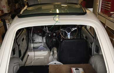
This is turning my shell back to a finished car, i.e. lights, bumpers, interior, brakes, fuel system, interior, etc. I often come up with unexpected problems, and have to find solutions in order to go forward! I don't always find time to work on this, hence the gaps between dates!! Also this is my experience, warts and all. Sometimes I've made mistakes and had to subsequently correct them. Hopefully this may help others from falling into the same pitfalls!
To go to the latest post click here.
Wednesday 9th January, 2019
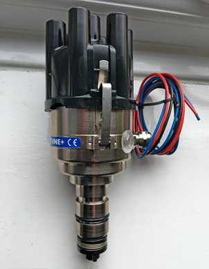
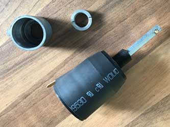
The 123 Ignition TUNE+ electronic distributor arrived from SC Parts Group. I ordered this as a replacement to the existing Delco which, according to Martin Jay of Distributor Doctor is "poor quality, Lucas units were much superior". This dutch made 123, which is configurable by an App in my iPhone, doubles up as a security device as a simple click in the App can immobilise it! First impressions are that it is extremely well made and finished.

Monday 28th January, 2019
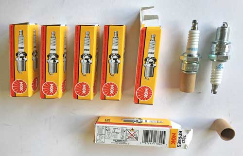
Now I've bought a new distributor, I've decided to upgrade the rest of the ignition system i.e. spark plugs, coil and HT leads (see below). To find our more see my Ignition (Latest Restoration 2) page or click here.
Thursday 31st January 2019
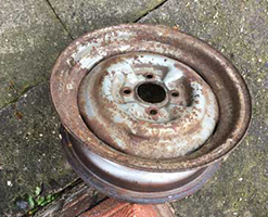
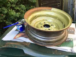
As I had some new tyres fitted to our Honda Civic at Hoole Tyre & Exhausts, I took the opportunity to take the spare wheel from the GT6 to have the old Michelin X tyre removed, so I can refurbish the wheel prior to getting a new tyre fitted.
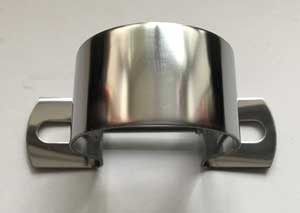
Today I also received the new stainless steel coil bracket from Mini-Spares.
Friday 1st February 2019
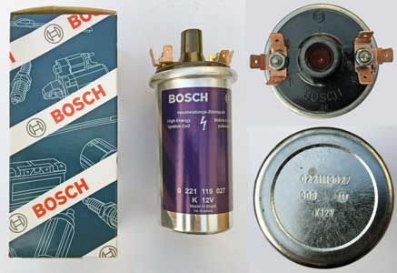
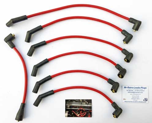
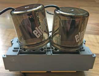
Just received the Bosch "Blue" coil (from the Green Spark Plug Co.) and the HT leads (from Mr-Retro-Leads-Plugs).
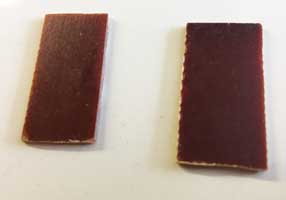
The top and bottom of the coil are shown as apparantly there are a lot of "bogus" blue coils out there according to Richard Atwell (www.ratwell.com). He says that the only Bosch Blue coil worth purchasing is the one made in Brazil. It can be identified by 4 tests: :-
1. It has a part number stamped into the bottom.
2. It comes with 3-way male terminals on both posts.
3. If you shake it you won't hear any oil sloshing inside.
4. It has the higher 3-4 Ohm primary resistance.
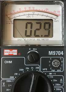
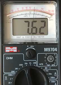
According to Accuspark "If the coil does not have standard or ballast written on the front you will need to test with a multimeter. Set meter to ohms, test between + and -. A standard coil will read around 3 ohms, a ballast coil will read around 1.5 ohms". I tested the new coil with a multimeter, and it read 2.9 ohms which means that is a standard coil (as recommended by 123 Ignition). This is the primary resistance (2nd picture below). The 3rd picture shows the secondary resistance (between the central output for the distributor and the +ve terminal).
Below are the new HT leads.
Tuesday 12th February 2019
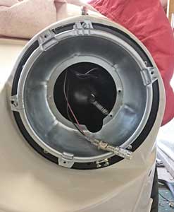
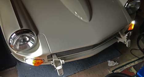
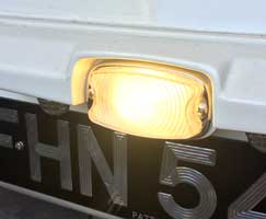
First outing this year (due to the mild weather). Tackled the headlamp again, but switched to the LH/NS. After some fettling, finally got it together. The adjusters had to be screwed right in before the chrome rim would fit, and even then it could do with being a bit closer to the bonnet at the bottom, perhaps adjustment to the clip will be necessary.
Saturday 2nd March 2019
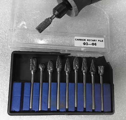
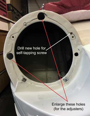
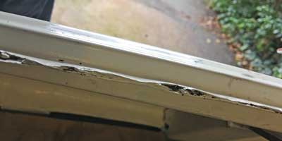
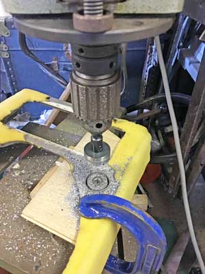
Worked on the RH/OS headlamp again. The problem is that whatever Southside Classic & Custom did to the bonnet, there is no longer sufficient room for the headlamp to fit, its too close to the bonnet, so although I don't like doing it I've had to 'bodge' it to fit! First, I had to enlarge the holes for the adjusters (and rubber headlamp gasket protrusions in which they fit) using a carbide rotary file in my Dremel Then I drilled a new hole (as indicated below). This was to allow the whole headlamp assembly to be moved to the left (looking from the front) so there is enough room for the rim to fit.
Monday, March 4th 2019
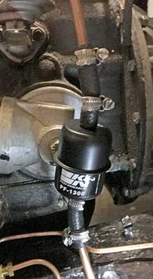
Did a bit of unplanned tidying (due to lost or missing 'rim kit' for securing the other headlamp rim). Didn't find it, so sent an email to James Paddock from whom it came to see if they can supply a replacement! Then, in order to achieve something useful I fitted the new K&N fuel filter (see below).
Saturday March 16th 2019
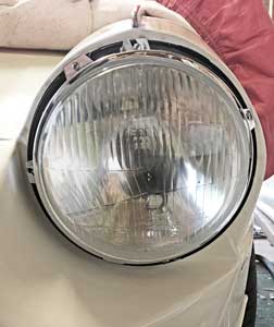
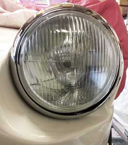
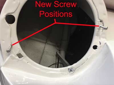
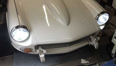
Finally fitted the RH/OS headlamp. In order for it to fit, I've had to move it from its allocated position to the left (looking from the front) so have drilled another new hole for a self tapping screw, see below left with both screws in position. The finished assembly can be seen below right.
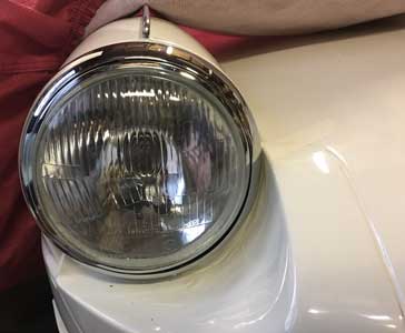
Below, a view of both headlamps.
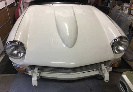
Next, to wire them in!
Thursday March 21st 2019
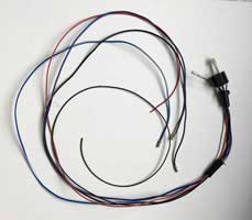
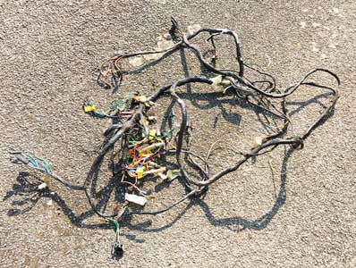
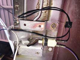
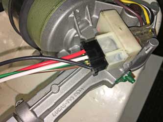
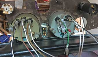
Wired in the recently fitted headlamp, see loom below.
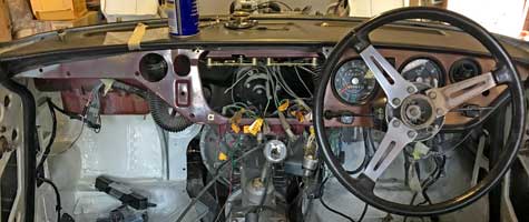
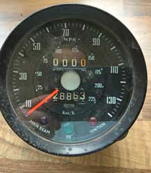
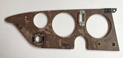
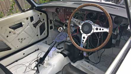
I tried to start the engine, but no fuel reached the carburettors. Eventually I found that the petrol pump was not working, priming it with the lever caused no petrol to come out, also while priming felt no suction sound! It's only 2013 when I bought it, perhaps little use has not been good for it! Ordered another one from Rimmer Bros, along with replacement window rubbers for the rear opening windows. These are really unobtainable, but the 'Brothers' sell something which hopefully will do the job. Finally started to remove the wooden dashboard starting with the bit on the left (with the SCCA plaque). I've got a refurbished dashboard to fit, and I'll be removing the wiring loom when it's out, and sending the tachometer away to be converted to electronic (as the 123 distributor has no mechanical rev counter take off).
Saturday March 23rd 2019
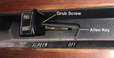
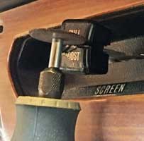
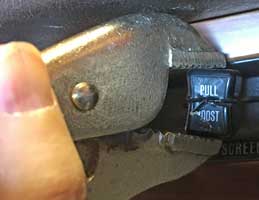
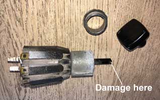
Started to remove the central part of the dashboard, but the 'Pull Boost' knob won't come off, the 1/16" allen key which removed the 'Hot Cold' knob fine just turns and turns on this knob. Either the grub screw is knackered or the thread in the knob is. I'll have to destroy the knob to get it off. I can easily get a new knob (Paddocks sell them for £4.25) but not the 'Pull Boost' transfer, so I've ordered one from ANG Classic Car Parts who have remanufactured these.
Monday March 25th 2019
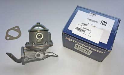
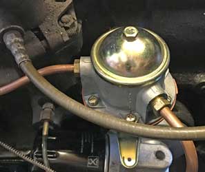
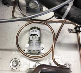
Fitted the new fuel pump (exactly like the old one) - both made by or branded 'powertune' and made in Taiwan (see below left)! On fitting there was a noticeable sucking sound as the lever engaged with the cam. Car still wouldn't start so checked electrics and found that the white wire from the +ve terminal of the coil to the ignition had come adrift! Then it started (first time in 2019) so ran it for a few minutes until the temperature gauge started to creep up. New pump installed, below right. Also visible the tachometer cable which will no longer be needed when I've had it converted to electronic. Unfortunately ran out of time, so unable to take the car out of the garage, so I hope the brakes are free!!
When I get a chance, I think I'll dismantle the old fuel pump to find out why it failed after such little use.
Tuesday March 26th 2019
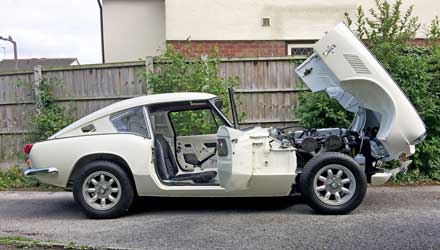
Had an hour to spare this morning so I got the car out of the garage! Fortunately everything still seemed to work, including the brakes! I need to adjust the bonnet front (its a bit low on the right-O/S of the vehicle, see larger gap on the left-N/S).

Wednesday March 27th 2019
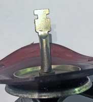
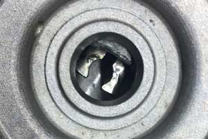
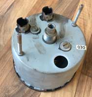
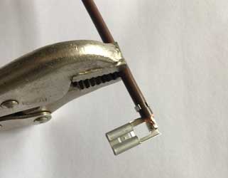
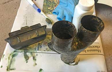
This evening I dismantled the Petrol Pump on the Kitchentable:-
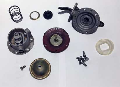
It appears that the metal rod (bottom left, with engagement slots) attached to the red rubber diaphragm is supposed to engage with a slot inside (bottom right, connected to the lever on the camshaft as well as the priming lever). This was not engaged properly and came out easily. When I re-assembled it and turned it 90 degrees so it engaged properly, there was an immediate suction sound when priming. So nothing had actually broken, more it hadn't been assembled properly, or more worrying, the part with the slot had worn or wasn't the correct size and the metal rod had become partially disengaged.. Although the pump now 'works', I wouldn't trust it back in a car! One begins to think that the build quality of some of these reproduction parts is not as good as the originals.
Thursday March 28th 2019
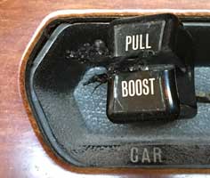
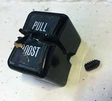
Successfully removed the PULL/BOOST knob from the heater controls by cutting with a dremel. I even recovered the grub screw!
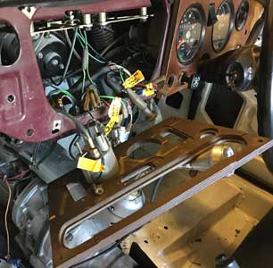
Then started unplugging and labelling the wiring at the back of the central part of the dashboard. I am replacing all the wiring, but decided to label the old just in case I need it!
Saturday March 30th 2019
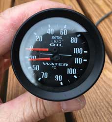
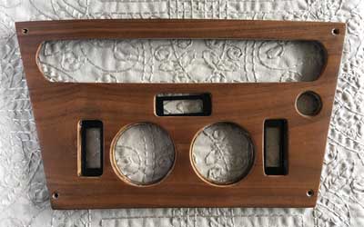
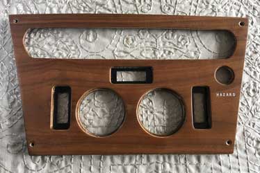
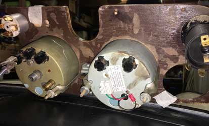
Managed to disconnect the oil and water lines for the combined oil pressure/temperature gauge, the last hurdle to removing the central section of the dashboard which is now out.
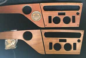
Below the old (top) and new (bottom). I need to apply a 'HAZARD' transfer, and move the SCCA badge.
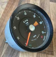
Next I've removed the tachometer to send to JDO Instruments to convert to electronic.
Monday April 1st 2019
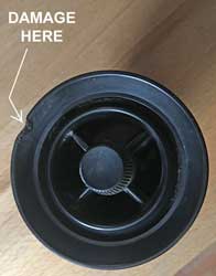
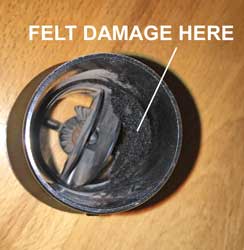
Not a good day! I finally managed to remove the right hand dashboard, but with great difficulty as the right hand air vent (officially "Louvre, face level", part number 713040, no longer available) wouldn't come out. I had to resort to force and managed to damage both the louvre and the dash. The dash is to be replaced, and in any cast the damage is easily repaired by filling and re-veneering (which it needs), but on examination, although the damage to the louvre is small, inside the felt is coming away. I've put in a bid on ebay for another pair of louvres (I can select the best 4 from the 6 I'll end up with, if I win) - the Louvre, foot level vent is the same part number.
Thursday April 4th 2019
Another bad day yesterday (yes, another one!) when the Honda broke down (2nd time in 3 weeks) on the way to visit my old Dad in Ruthin. Spent 3 hours in a layby near Penymynydd with Liz, Maddie, Cleo the dog and a chocolate cake! Honda Assist sent out the AA, and to be fair the bloke who came was great. A coil pack had failed, and no spares were available - he went into Chester to get one, and on the way back had to return it when he discovered the one inside the box didn't match the description on the outside. They cost around £100 each, and there is one for each cylinderm thank goodness Triumph spares are a little cheaper. He then tried to tow me but that failed (car too low). Finally he magicked a trailer out of the back of his van, and, after friend Linda transported the family home, took myself and stricken car to Cheshire Oaks Honda. Fortunately the car is still under warranty so 4 new coilpacks will be fitted tomorrow morning, as I was concerned that if one had failed (probably when the car overheated 3 weeks ago) others would follow.
This afternoon I managed to get the remains of the dashboard off by disconnecting the Hazard switch and the WindscreenWiper/Washer switch, although I couldn't get the knob off the latter (it's supposed to be pull off). I eventually broke the end of the plastic spindle pulling off the knob. Put in a bid on ebay for another.
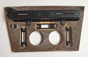
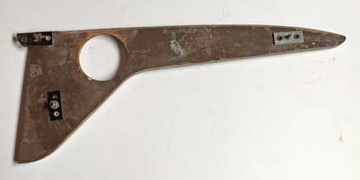
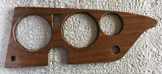
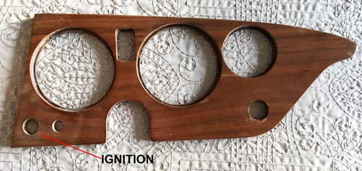
The old and new dashboard can be seen below.
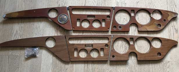
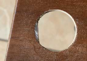
The damage (top right) can be clearly seen. I need to drill holes for the ignition switch and the choke (bottom right).
Saturday April 6th 2019
Taxed car for a further 12 months to 30th April 2020.
Monday April 8th 2019
I received the two 'louvres - face level' bought from ebay. Their condition exceeded my expectation so they can be used in the new dash, keeping the others for the under-dashboard down vents. Yesterday I also won a replacement 2-speed windscreen/electric washer switch from ebay. This means I can electrify the washer, using a similar motor to that used with later Spitfires. The switch is almost identical to the original (with its pump action wash) so I think this will be a worthwhile modification.
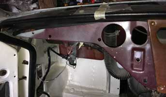
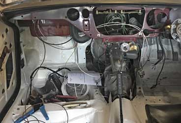
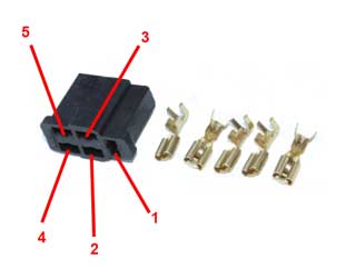
Finally got the loom out of the car. I now need to identify and order the cables and connectors for the Ignition circuit (I'm doing a circuit at a time, making sure everything works before going on to the next circuit). Getting the engine going is naturally a priority! Most is labelled so I know what connectors etc I need.
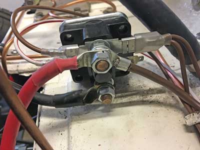
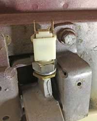
I later spent some time working out where the 4 brown wires connected to the live terminal of the solenoid go to, as 2 are linked into a wide spade terminal and 2 more are linked to a normal spade terminal. There are also 2 different wire thicknesses involved!
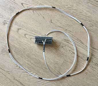
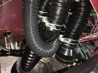
Tuesday April 9th 2019
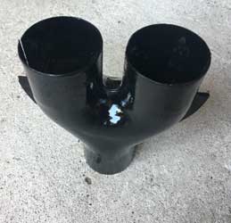
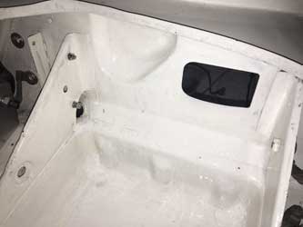
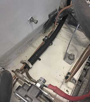
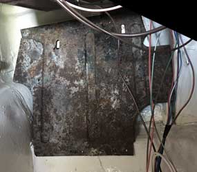
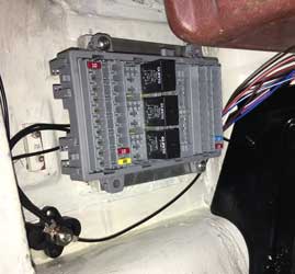
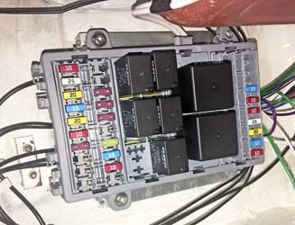
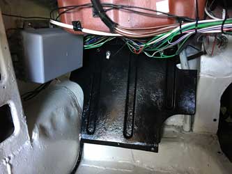
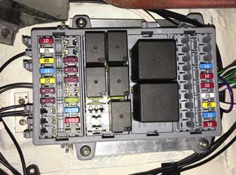
Did bits & pieces. Cleaned, sanded and painted one of the two Y Piece Heater Tube Assemblies. Sourced some replacement ducting - note that two internal diameters are used - 1.1/2" and 1.3/4" (38mm and 45mm). Both available from Autosiliconehoses.com. I then painted inside the battery box and the area adjacent to the old fuse box, which was removed with the loom, ready to install a new fuse box. I am installing a completely new multi-fusebox in the passenger footwell, but I will still fit an original style fusebox in its original position for appearances sake, and also to continue to use it as a pass-through for the cables going along the scuttle to the starter solenoid. It just won't have anything connected to it!
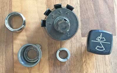
Today, I also received the wiper/washer switch - I think it's from a TR6. Testing with a multimeter showed all working as it should. It seemed to be in good condition, even the knob has clear markings! I've partly dismantled the switch, the numbers for the terminals can be clearly seen: 3 is the live feed (which will be fused); 1 is 'park'; 2 is the slow speed and 4 is the fast speed.
Wednesday April 10th 2019
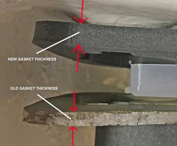
Tried to fit the new fusebox, after fitting the old fuses to the new box (for appearances!) but the gasket was far too thick for the lugs to engage. I therefore put it in a heavy vice between two pieces of wood for a few hours.
Thursday April 11th 2019
Finally ordered the cables from Vehicle Wiring Products for the Ignition system. I sent them an email query which they have not responded to about the cable to use between the alternator and the solenoid (battery, really) after realizing that a 60 amp alternator should have a thicker wire than the original 35 amp. In the end I erred on safety and ordered 8.5mm2 cable (which takes up to 63 amps) even though I had reservations about it being too thick to fit in the alternator connector. According to AES the specification of this cable is "120/0.30, 8.5mm², 63.0A - cable OD 5.5mm". I tried to order from them, but unfortunately they don't have the colour range VWP have. When the cable comes, I'll have to 'suck it and see'!
Friday April 12th 2019
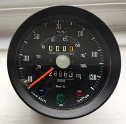
Received the tachometer converted from mechanical to electronic drive by John Ostick (JDO Instruments) see below.
I've also fitted the fusebox, with the 'flattened' gasket:
Saturday April 13th 2019
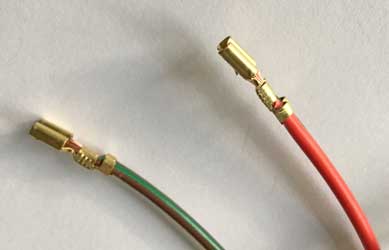
Received the first batch of cables from VWP so made a start on the wiring. I have split this into sections (see Latest Restoration2 - Electrics) and the first is the most important, the Ignition Loom. When this is complete I should be able to start and drive the car! First, I did the Alternator connections (see below). As well as crimping the flag terminals I also soldered them. The main feed wire (the thickest brown) is connected to the solenoid by a ring terminal, which I forgot to order! However I did a couple of the brown cables connecting the solenoid (linked together on one spade terminal) to the alternator and the ignition.
Monday April 15th 2019
First, I modified the tachometer, glueing on a connector block to facilitate the connection of this to the loom.
I also fitted a couple more cables to the alternator, another brown which goes to the fusebox, and the red/white which goes to the ignition switch - this will trigger the solenoid to operate the starter motor.
Wednesday April 17th 2019
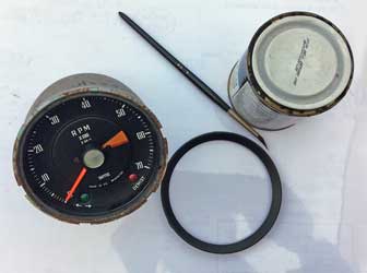
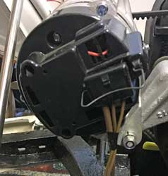
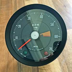
Some renovation work on the tachometer, which needed it! Below, before and after. Fortunately JDO had removed the front to do the conversion, so it was easy for me to do likewise. Next, the speedometer, which I suspect will be more trouble!

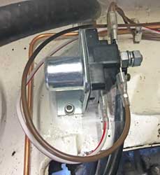
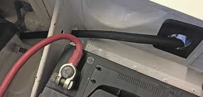
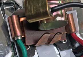
The solenoid is now fully wired up:
The thick red and black wires (top and bottom) go to the battery (red) and starter motor (black). The white/red wire on the left goes to the ignition switch to activate the starter when the key is turned against the spring. The thick brown wire on the right goes to the alternator, the main feed. The twin smaller brown wires, also on the right go to the ignition switch and the alternator again (to 'energise' it, apparantly. The top terminal is effectively the main +ve terminal, a neater solution to connecting directly to the battery. The brown wire on the left goes to the fusebox for items which can be used when the ignition is off.
I now have completed the ignition connections, and passed the 'acid' test, the car starts and runs!
Thursday April 18th
Removed the bezel from my Speedometer and cleaned it and the glass and then repainted it. This YouTube video was most helpful (click here to see it). Below, before and after.
Friday April 19th 2019
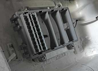
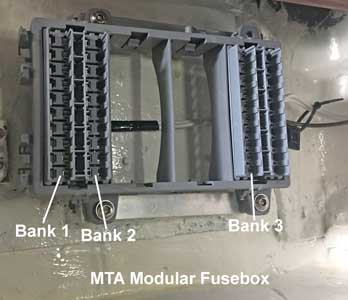
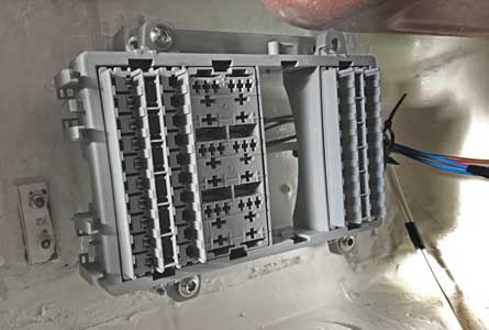
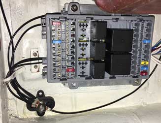
Started work on the Fusebox (MTA Modular), see below.
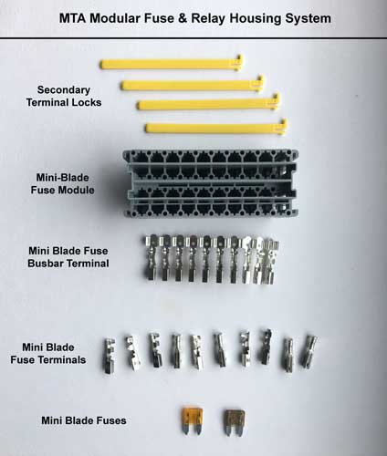
First I soldered one of the white feed cables from the ignition to the strip of busbar terminals. Then I attempted to insert the busbar terminals into the Mini-Blade Fuse Module. It was extremely tight! When I finally got it in, it didn't look right, and wasn't inserted enough to get the terminal lock in. I then removed it, probably destroying both parts! Looking at it, I came to the conclusion that it was designed so they would only fit when the 10 terminals had been crimped, which they would not be as only one or more would need to be connected to a cable. This is a problem when no instructions come with the stuff. The best information was on the VWP website which simply stated " Terminals are crimped or soldered onto the cables then pushed into place. Tabs on the terminals latch them into place". This probably refers to individual terminals, not terminals connected together onto a Busbar. So to find out I had to destroy both a module and a busbar! The busbar below was ripped out of the module, the non-crimped terminals can be clearly seen.
Saturday April 20th 2019
I soldered a cable to another busbar, this time with all the terminals being flattened with pliers (I couldn't physically get my crimping pliers in as the other terminals got in the way). This finally fitted into the fuse module, and the was locked in with the terminal lock. I then repeated this with the other white cable (both main feeds from the ignition switch to the fusebox). I then fitted the module into the fusebox, and fitted the fusebox into the car, albeit temporarily, with the wires going to the ignition switch.
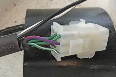
The next job was changing my loom front/rear connection from original (which had required a lot of wire-joining) to a more modern Mate-N-Lock connector. I did't use this at first as I was concerned that they have a max load of 10 amps. However the only big draw would be the Heated Rear Window which uses a separate wire (see below, also an earth).
Sunday April 21st 2019
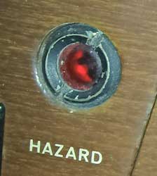
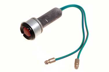
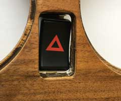
'Visit Dad Day' today, so not much done. Checked the bulbs etc for the dashboard and discovered the Hazard Warning Light is missing! I've got so many parts in boxes in the house and the garage!! Looking at a photo it was in pretty ropey condition, so I spent a while on the internet trying to buy a replacement. Nothing on eBay and most suppliers state 'no longer available'. This was also fitted to the TR5 and early TR6 and I eventually found a used one on Rimmer Bros. website - it's extraordinary what these people sell that no one else bothers with - they should be applauded for this. Below the original (left) and the replacement (right - from Rimmer's website) which hopefully will be in much better condition. Incidentally Rimmers don't list this for the GT6 so I hope it fits. The part number is correct, 148830.
Wednesday April 24th 2019
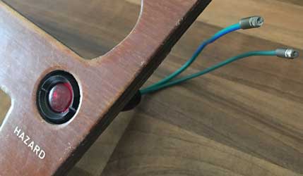
Although my next project is to start assembling the wiring for the Lights Circuit, I looked ahead at the Indicator/Hazard Circuit, and when trying to work out how to wire in the electronic relays supplied by Classic Car LEDS, I discovered that there was no provision for a warning light, and to incorporate them into my circuit I would need bridge diodes etc. After a quick email to Classic Car LEDs, proprietor Duncan Rickards very quickly responded with a suggestion that I use a different relay. I quickly ordered these, along with a variety of LED bulbs - I intend to fully convert the GT6 to LED where possible. The only difficulty which may arise is (1) the new relays look taller than the ones I've got and may not fit under the cover of my MTA modular fuse box, and (2) there is a separate earth wire which I will have to accomodate. The replacement Hazard Warning Light arrived; it fits perfectly and looks in much better condition than the one I had originally.
Friday April 26th 2019
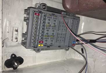
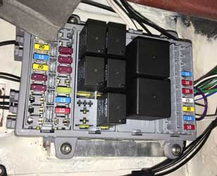
Having received a new fuse module from VWP, I soldered the brown wire from the Solenoid (permanently live) to another busbar, which I successfully installed into the module, which I mounted back into the car. Banks 1 & 2 are connected by white wires to the ignition switch, and Bank 3 is connected by a brown wire to the solenoid - so is permanently live.
I also received a package from Classic Car LEDs including the new relays which have a separate terminal for the warning lights. However these would not fit into the module, see below.
I then decided that I would have to redesign the Hazard & Indicator circuit with my existing relays which do fit into the module. I did this and overcame the problem of the indicator warning light connecting both the left hand and right hand circuits by using a diode bridge, fortunately I had one lying around that I obtained from Better Car Lighting but which I did't need. I sent the circuit diagram to Duncan Rickards and fortunately he found it to be ok. You can see a copy by clicking here. I must say that the service I have had from Duncan and his company Classic Car LEDs was excellent and I can't recommend them enough!
Saturday April 27th 2019
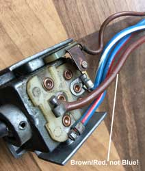
Poured with rain today, and a cold wind (around 7 degrees) so most work indoors! I fettled all my circuit and loom drawings and my cable list (all individual cables are numbered). I tried to test the steering column headlight flasher switch, and in the end had to take it off to test inside! It turns out it all seems to work satisfactorily - When Brown/Red & Blue/White connected - FULL BEAM; When Brown/Red & Blue/Red connected - DIP BEAM; When Brown & Blue/White connected - FLASHES! The puzzle of the wire colours was solved, what is on the official wiring diagram as a Blue wire is in fact Brown/Red. Why this is the case I'm not sure - perhaps the switch is from another car with slightly different wiring. However the Brown/Red wire will be connected to a Blue wire in my Loom.
Monday April 29th 2019
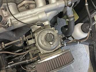
Today I put back the steering column flasher switch - it was a lot harder than removal, especially as I missed out a spring clip (609639) which had slid down the column. I had to take it all apart again and re-assemble it! Then I fitted the remaining wires of the Ignition Loom, and was pleased that the Ignition Warning Light worked - except that I couldn't start the engine with the thermostat housing dismantled. This is so I can fabricate a spacer to raise this slightly as the water hose catches on the water temperature gauge capilliary tube.
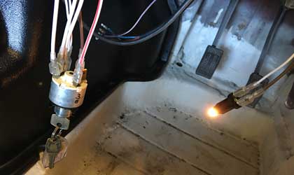
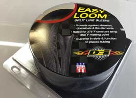
Next I fitted some "Easy Loom" around the cables going to the Solenoid.
I need to fit a grommet to the "Fusebox" hole. I intend to do this my cutting it, inserting it around the cables and then superglueing it back together before inserting it into place.
Monday April 30th 2019
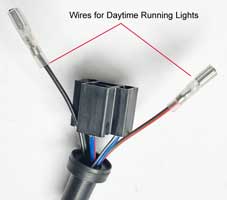
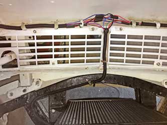
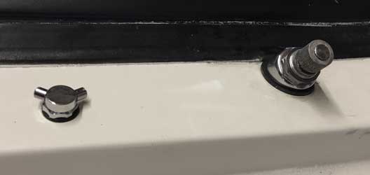
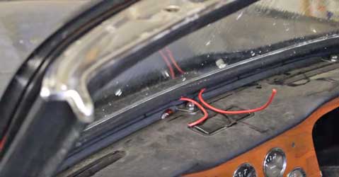
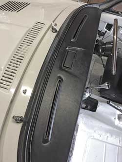
Installed the first cable of the Lighting Circuit, the earth from the DRLs and Headlamps to the bulkhead by the battery. I considered putting an earth cable onto the fromt indicator/sidelights, but in the end settled on an additional earth post (bolt) each side of the bonnet with the earth wires from the DRL and headlight attached using ring terminals. This would enable me to connect these wires together with an additional cable going to the front (see pictures below). This would also give an additional earth connection to the front indicator/sidelights which would obviate the need for an additional one! Does it need one? Earthing through bodywork can be a little unreliable in my view, I prefer the belt and braces philosophy. I'll check it with a meter.
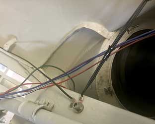
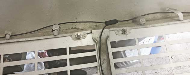
I've just realised that I've used the holes meant for the Horns! The new air horns I'm fitting will only need to go on the LHS, so I may need to move this bolt!
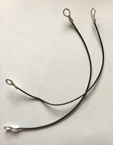
Thursday May 2nd 2019
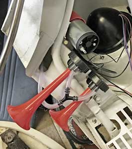
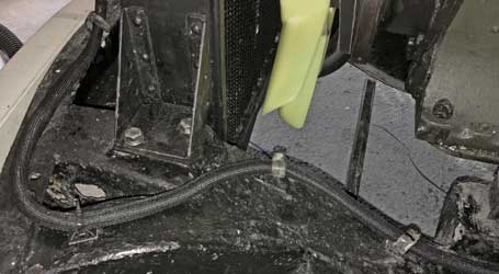
Yesterday I checked with a meter that earth was reaching the front indicator/sidelight assemblies, and it wasn't. I therefore made up a couple of cables to connect the fixing setscrew of these assembles, with an additional nut, to the earth posts previously fitted to each side of the bonnet. I've also unpacked the Fiamm air horns and worked out that one of the bonnet fixing bolts in the left wheel arch can be used to fit the air compressor inside the wheel arch. The earth connection for this can also go to the earth post!
In the afternoon I fitted the leads above, and also (as it was in the same vicinity) the air horns, the compressor fitted in the wheel arch space, and the bolt for one of the bonnet tubes was replaced with a longer one, and this was ideal for fixing it. On testing they were quite loud!!
Friday May 3rd 2019
First, I unpacked my first lot of LED bulbs from Classic Car LEDs. Although they appear to be very high quality bulbs, they were all packed with no labels so I had to spend some time determining what they were! The top left are front parking lamps, but these should be BA9s (although the workshop manual said BA15) so will have to be returned. The top right are for my additional rear brake lights. The others are labelled below.
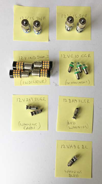
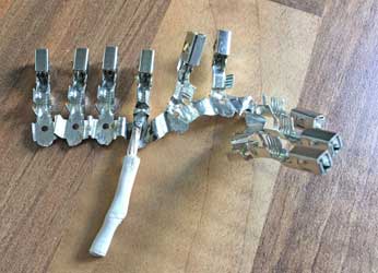
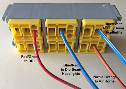
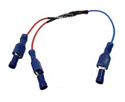
I prepared 4 cables for the Lighting Loom, the DRL, Main Beam, Dip Beam and as I had just fitted it, the new Horns. These are shown below. The yellow bits of the relay module have to be removed (with a very small slotted screwdriver) and the wires crimped onto the terminals which click into place. The yellow bit is then re-inserted to secure them.
Monday May 6th 2019
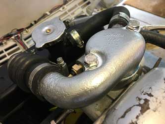
I finally fabricated the spacer to raise the thermostat housing around 4mm to facilitate the insertion of the capilliary water temperature sensor, which previously fouled the top hose. It is made from 3mm aluminium.
![]()
![]()
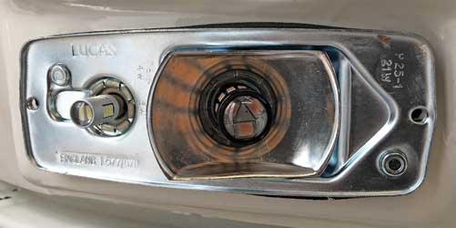
Finally I fitted the LED bulbs in the front RH sidelight/indicator. The indicator bulbs are amber, as when LED bulbs are behind coloured 'glass' it is recommended that they are of the same colour, so they look authentic.
Friday 10th May, 2019
Completed all wiring at the front, just need to tidy it up and add Easy Loom™.
Saturday 11th May 2019
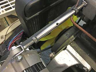
Having just received the 5/16" x 2" bolts from Grove, I refitted the thermostat cover. The original bolts were 1½" long so I intended to cut the new ones down to 1½" + 4mm (the 3mm spacer plus 1mm for the additional gasket) = 42mm long. However I discovered that they protruded from the bottom, so didn't need to be cut down. I replaced the top hoses and clips and refilled the radiator. My son brough back the battery charger he borrowed, so I put the car on charge, ready to start up in due course. I also fitted new fibre washers to the Alternator turnbuckle, as these kept coming loose when the engine ran.
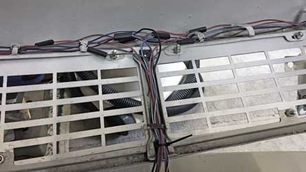
My next job was to encase the wires under the bonnet in Easy Loom™. This took some time as it was a fiddly job! However it does a neat job, and enables me to wire the car in sections, rather than build a loom on the workbench.
The front of the bonnet looks quite busy - there are 8 wires: Sidelight, Left Indicator, Right Indicator, Full Beam, Dip Beam, DRL, Horn & Earth (everything is separately earthed). Note that I am still using 'old fashioned' bullet connectors.
Tuesday 14th May 2019
Busy day today, taking Dad to hospital, collecting Maddie from school & collecting Katie's car which she had left at work, but had half an hour so I took out the LHS heater control (with the Pull/Boost knob) to understand the heater circuit, see Heater.
Friday 17th May 2019
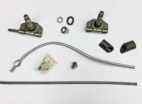
Replaced the LHS heater control. Then I removed the wiper wheel boxes, the wiper tubing and the rack cable. These were all cleaned (the last part of the rack tubing before the motor was repainted) and seemed to be in good condition, well greased and no sign of wear in the rack or wheel boxes, so were re-assembled and replaced onto the car with a new wiper bezel kit.
Saturday 18th May 2019
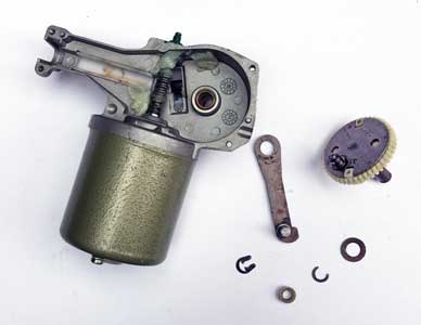
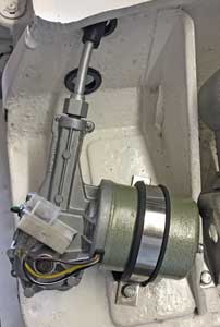
Did quite a bit today - finished fitting the wiper rack and wheel boxes - I had to remove and refit as one of the rubber spacers fell off one of the wheel boxes during fitting yesterday as I discovered when I screwed down the large nut to find it went down further than it should! I then fitted the new wiper motor I purchased ages ago from Rimmers. It didn't have any gears, these were removed from the old motor, cleaned up, regreased and fitted to the new. I finally started the engine and apart from an annoying fuel leak from one of the pipes going to the carburettors, which I replaced, there were no leaks (of water). After 5/10 minutes the top of the radiator was still cold so I carefully removed the radiator cap and topped up the coolant. Running the engine again the radiator became hot. I tried to reverse the car out of the garage until I realised that there was no steering wheel fitted!! I also fitted the new washer nozzles and tubing, also fitted the washer motor.
Monday 20th May 2019
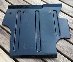
Today I hunted for the passenger Heel/Toe Board or Passenger's Footrest Panel (810252) as it is virtually unobtainable now! Fortunately I found it on an upper shelf of the garage - then I had to work out how it fits! It was very rusty - so I've sanded it down and repainted it.
Wednesday 22nd May 2019
Just did some more wiring on the lighting circuit. Just earths, final connections to steering column, fit relays and LED bulbs, before testing. Below, 5 fuses fitted (although I need to turn them around!). The new earth post can be seen bottom left.
Saturday 24th May 2019
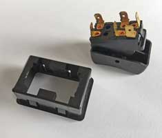
Completed the Lighting Loom/Circuit and fitted the Relays and the LED bulbs. Then, the crunch - testing! First, I discovered I'd wired the Master Light Switch to a fuse which is only live with the ignition on, so the sidelights couldn't be turned on without the key in the ignition - easily rectified by moving to another fuse on the bank connected to the soilenoid (permanently live). Also it played up, but I discovered that this was due to a faulty master light switch. Eventually I got it to work as designed by switching on and off a few times, but I've ordered a new master light switch from ebay. When it works it does the following:
| Ignition On | |||
| Master Light Switch | DRL | Sidelight | Headlight |
| Off | On | Off | Off |
| On - Position 1 | Off | On | Off |
| On - Position 2 | Off | On | On |
| Headlamp Flasher | Works! | ||
| Ignition Off | |||
| Headlamp Flasher | Works! | ||
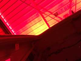
Above, with the ignition on the DRLs light up. Below with the sidelights on, the DRLs go out.
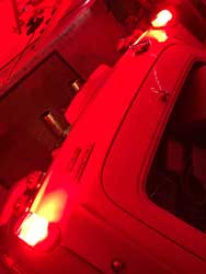
Similarly with the headlamps.
The LED lights are certainly bright!! In fact I am a little concerned about the spillage of the light to the rear bodywork next to the rear lights (see above, right) - I've emailed Classic Car LEDs about this, perhaps I need to add some additional reflecting foil inside the rear light lenses.
Saturday 25th May 2019
| Ignition On | ||||
| Master Light Switch | DRL | Sidelight | Headlight - Full Beam | Headlight - Dipped Beam |
| Off | On | Off | Off | Off |
| On - Position 1 | Off | On | Off | Off |
| On - Position 2 | Off | On | On | On |
| Headlamp Flasher | Works (Full Beam only)! | |||
| Ignition Off | ||||
| Off | Off | Off | Off | Off |
| On - Position 1 | Off | On | Off | Off |
| On - Position 2 | Off | On | On | Off |
| Headlamp Flasher | Works (Full Beam only)! | |||
Moved the Master Light Switch input to a fuse on the permanently live part of the fusebox. Now, everything works as it should - now on to the next circuit, the Indicator/Hazard lights.
Saturday 1st June 2019
Did a bit of work on the dashboard components.
Below, assembled onto the dashboard sections.
Monday 3rd June 2019
Started doing the wiring for the Indicator & Hazard circuit.
Thursday 6th June 2019
Completed the Indicator & Hazard circuit.
On testing the indicators work fine, but the Hazards work only on the LHS only! I swapped the wires on terminals 6 and 3 on the hazard switch and the hazards then worked on the RHS only. I swapped them back and they now work properly - there must have been a bad contact in the Hazard switch. The indicator warning light flashed as well as the hazard warning light, but that's ok. Testing the indicators again, they worked but both the hazard and indicator warning lights came on with the left indicator only - I'll have to re-check the circuit - but I didn't expect everything to work perfectly first time.
I've checked the circuit, and found the cause of the error! There's a link between the LH switch on the steering column and the Hazard Warning Light! This link is needed, but in one direction only, so I will have to incorporate another diode bridge into the circuit, so I quickly put in an order to Classic Car LEDs.
Later, I finally discarded the leaking Teflon petrol pipes, and replaced them with Gates 'Barricade', ethanol proof pipes fixed with double ear 'O' clips which look neater than jubilee type clips!
Friday 7th June 2019
Received the additional diode bridge this morning from Classic Car LEDs - amazing service!! I removed the nasty insulated connectors and replaced them with bullets. I had to spend a couple of hours rejigging the circuit and loom diagrams. To see the new circuit click here. Fortunately I labelled all the bullet connectors with letters of the alphabet, so re-connecting all the wires into a slightly different circuit was straightforward. On testing it now works exactly as designed, although the Hazard switch will need replacing - sometimes all 4 lamps flash, other times one side only!
Saturday 8th June 2019
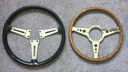
Not much, today - just de-rusted the ash tray and one of the Y pieces from the heater assembly. I also started looking at the horn, the next circuit I will wire up. I will need to remove the old steering wheel boss as I've got a new Moto-Lita one to replace it with. Also the top spring connector is missing, so that's something more to buy - it's incredible how many unplanned bits and pieces need to be purchased in a rebuild like this!
Monday 10th June 2019
Managed to remove the steering wheel. Internet Forums seem to be of the opinion that the best way (short of purchasing a puller) is to unscrew the central nut (initially very tight) until it is nearly flush with the threaded column, grip the steering wheel, give a couple of sharp taps to the centre (the nut protects the thread) with a hammer and bingo! Well I tried it, pulling the steering wheel (which I'd had to refit) towards me with one hand and my knee, and it did come away when the hammer was used a couple of times. Unscrewed the nut and off it came. Then I tried the boss which came with the Moto-Lita steering wheel and it was plainly too small - I'd got a B20H (GT6 early) when I should had had a B20AH (GT6 later). An email to Rimmer Bros elicited an immediate response from Steven who agreed to exchange it - great service considering it is 16+ months since purchased and it was my fault.
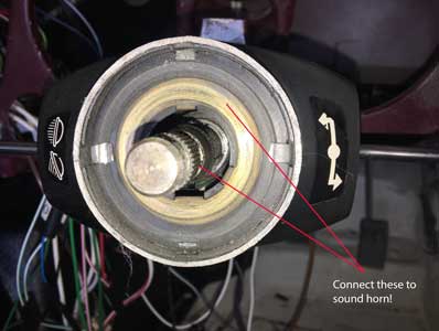
I then connected all the cables for the horn, and by putting a pair of pliers from the brassed ring in the column to the centre of the column (see below) mimicked the horn push when it's installed, and it worked a treat.
Monday June 17th 2019
Some problems today! Received the replacement boss from Rimmer Bros - I am very impressed with their service which is excellent. Although the box was labelled B20AH the actual boss had B20A engraved onto it. I fitted it. although it was a bit tight on the splines, needing a good tap to go on. The horn now works a treat when the button is pressed. Finally I tried to turn the steering wheel (I had to partially fit the wheel to the boss for this) and it was met with some resistance - something must be catching somewhere. I was disappointed by this so I sent an email to Moto-Lita Ltd. I had also ordered a replacement hazard switch from Rimmers. At first this appeared to be the wrong one. However on further examination the switch came in 2 parts, and removing the outer part enabled it to fit the metal bracket screwed to the rear of the dashboard, or it should have except that it catches on parts of the hole/cutout. This will have to be enlarged slightly with a file.
I fitted the green wire from the fusebox to the heater blower and on testing this works on both speeds - so no problems with this. My preparation in designing each circuit in great detail in advance is paying off, as when connected up things work first time!
Saturday June 22nd 2019
Connected a few more wires, awaiting more from VWP. Had a response from Moto-Lita's Director of Engineering Joe Kaluza re: my problem with the boss 'catching' on the top of the steering column - very impressed with their service! I've sent him the pictures below, awaiting his response, but to me the best solution is to slightly chamfer the top of the column with my Dremel and a small grinder.
Friday 28th June 2019
Finally got a response from Moto-Lita's Director of Engineering "I wonder if you have adjustment on your column? It seems odd as to why it is catching like that. If the fitment is secure and the nut tight, I can't really see what else you could do apart from what you suggest".
Connected Brake Lights, they didn't work and blew a 10 amp fuse! On investigation the Green/Purple wire seems to be connected to earth somewhere so when the brake lights are operated there is a short circuit! An investigation ensues, I'm a bit puzzled as the earth leakage is in the rear loom which had already been tested on 26/08/17 with normal filament bulbs. Finally after a lot of messing around checking the rear loom, I connected the earth wire to... earth! It now works. I had provided a separate earth for all the rear lights but as they worked fine with filament bulbs (presumably earthing through the bodywork) I never got around to connecting it. When all else failed I connected this and now it seems to works. It seems that earthing is particularly critical with LED bulbs - although I can't see how this lead to a short circuit! Fortunately all the front lights are separately earthed.
Saturday 29th June 2019
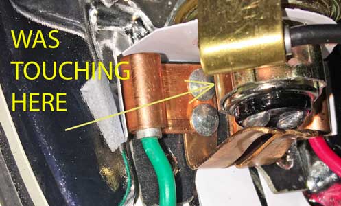
I was wrong! Turned on the brake lights this morning and the fuse blew again, back to square one! After a lot of fiddling about, I thought about yesterday when it seemed to work, and I realised not all the bulbs were in. I then found that it worked if I put the RH bulbs in but as soon as I put the LH bulb in the fuse blew. Close examination of the light unit showed that the earth and live were very close together - in fact they were touching. I levered it away with a screwdriver and now it all works a treat. Phew!! Perhaps these reproduction Lucas parts aren't as good as the originals and couldn't take the extra weight of the LED bulbs. Unfortunately I had no choice as the old units were 'well' rusty. I may well fit some sort of insulation to prevent a recurrance, perhaps a piece of plastic from an old credit card.
Monday 1st July 2019
First I cut out from an old piece of insulation material two small pieces and inserted them into the rear lights, to prevent any recurrance of the shorting problem.
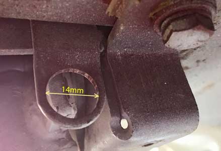
Now I've wired in the interior courtesy light, I need to fit the tailgate switch. However when I tried to get one a while ago I found they were unobtainable, but congratulated myself when I found what I thought was an identical one for a MGB GT. However when I came to fit it, I found it would not fit, it needs an aperture around 12mm in diameter wheras the hole is 14mm! I went to my local hardware store to buy some M12 washers, but on getting home discovered that the ID is actually 13mm! I've therefore purchased a couple of copper washers from ebay, 12mm ID and 18mm OD - hopefully the ID is actually 12mm! This would need to be soldered to the bracket on the tailgate (because it needs to be earthed) which sholud be fun!!
Wednesday 4th July 2019
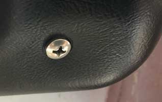
Received the washer I'd hoped would enable the tailgate switch to fit, but it was too small, although only by a fraction. Then I had a brainwave. I'd ordered a new stop light switch as I wasn't happy with the fit of the nut on the old one, I also ordered some 1/2"UNF half nuts. However the older stop lamp switch worked fine, so I fitted it in the tailgate instead of the 'proper' one which didn't fit (it was for a MGB GT). This works great, see photo below. I'll just have to find an earth to connect it to.
I then fitted the new stop light switch to the hole above the brake pedal. This turned out to be a pig of a job. First it was very hard to reach it, I had to remove the driver's seat (fortunately only resting in position) and crawl in with my feet to the rear and poke my head under the dashboard, avoiding the steering wheel indicator controls. At first the 1/2UNF x 5/16" nut kept cross threading because it was such a tight fit on the plastic thread. Fortunately I had a 1/2UNF die which I ran up and down the thread a few times to make the nut slacker. Eventually, after much swearing I did it and a quick test showed the brake lights worked perfectly - see reflection in the garage doors below.
Next, the interior light and the steering wheel.
Saturday 6th July 2019
Tried to fit the twin terminal door switches I bought but found that the spade connectors did not have enough room inside the A post. However by bending the terminals I have managed to get them to fit.

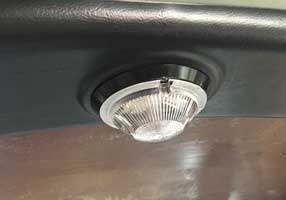
Connected wire from one of the bolts holding the rear tailgate to serve as earth for the tailgate switch and the Heated Rear Window (when fitted). Fitted the roof light (although it will have to come off again when I fit the headlining) and it works both with the LH door and tailgate opening.
I can't fit the switch to the RH door as I can't open it enough (inside the garage) and the dash switch is not yet connected to a switch, but I'm sure these will also work.
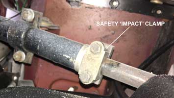
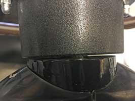
Monday 8th July 2019
Went to see my old man yesterday, and I thought about the problem fitting the Moto-Lita steering wheel and the response from Moto-Lita themselves regarding adjustment. So today I slackened off the lower safety impact clamp and found that there were a few millimetres of up/down adjustment in the steering column. Moving the column to the limit of this adjustment enabled the Moto-Lita boss, when fitted, to be well clear of the top of the column. The result of this adjustment can be seen below right. I also put a bit of black paint on the scraped column shroud so it is all looking good.
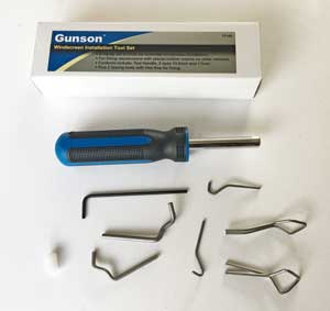
The next job will be the wiring for the HRW, I've also ordered the Gunson tool to facilitate the re-installation of the rear window (as favourably reviewed in Classic & Sportscar).
Wednesday 10th July 2019
Received the Gunson winsdcreen tool - I just need to work out how to use it, there are no instructions, even on Gunson's website!
Next I made a start on the wiring for the Heated Rear Window, fitting the relay and fuses.
Friday 12th July 2019
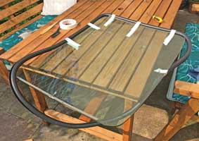
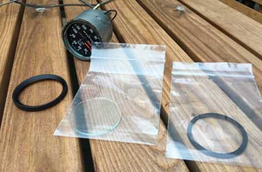
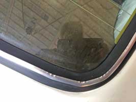
Just completed the HRW wiring. Put the window on the luggage area and connected it. Can't really check if it's working (need some mist to demist!) but getting voltage at the terminals. Next, I fitted the rear window seal in preparation to refitting the rear window. The first two attempts it was the wrong way around! Then I worked out how it went!
I wasn't sure if any sealer or sealant would be necessary (I don't remember using it before). In the end, after watching Elin Yakov replacing a TR6 windscreen on youtube, I decided against it. To see it yourself click here. The TR6 windscreen is identical to the GT6 one, and the procedure would be very similar for the rear window. However I decided to insert the rubber into the frame first and then put in the glass, which I think is the more common way of doing it. I may use Elin's method with the windscreen.
Tuesday July 16th 2019
Changed my mind, after seeing US Steele Rubber Products President, Matt Agosta, and Scott Goodwin from Goodwin Restorations remove and replace the back window glass weatherstripping on '67 Chevy pick-up using a cord on "My Classic Car with Dennis Gage". To see their video on youtube, click here. They did it like Elin Yakov, putting the rubber on the window first and using a cord. I'm attracted to this method as I can't find any videos using the Gunson tool, even on their website!
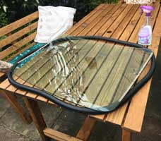
Failure! I removed the rubber from the car and put it around the window on my patio table. Quite difficult as it was reluctant to go on, then kept coming off. Eventually I used masking tape to hold it on!
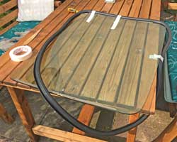
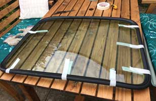
Then I tried to insert it into the tailgate. I put it in with some cord (from a strimmer) as per the videos. Pulled the cord while holding it down. It looked 'in', then when I examined the underside, it wasn't at all. The rubber was not over the innermost lip at all, and when I tried to pull it over it seemed so difficult that I gave up - removing the window entirely (it practically just lifted out). Back to square one.
In desperation I sent an email to Elin Yakov, but not sure he'll reply. I think I have three alternatives, either try again pulling the cord from the inside, reverting to putting the rubber in first, then the glass, still using a cord or getting a specialist in.
Wednesday 17th July 2019
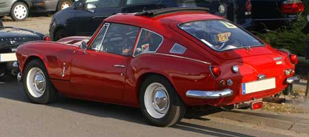
I tried again this morning by removing the rubber seal from the window and re-installing in the car. When I tried fitting the glass, the cord kept falling out - I'm obviously using the wrong cord (I used Strimmer cord) so I've bought a ball of cotton twine at great expense (£1) as nylon is not recommended as it can cut the rubber. Today I also received a very welcome email from another GT6 owner, who must have read this blog, with some advice so I'm going to try again. He has a superb Mk2, a picture of which is shown below.
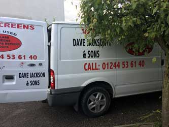
My latest attempt also ended in failure. I just couldn't get the rubber to go around the bottom lip of the tailgate (i,e, inside). I ended up phoning Michael Alexander a Triumph Sports car specialist here in Chester. He recommended a Dave Jackson who works for AutoSteer in Saltney, apparantly he specialises in windscreens. I then spoke to Dave and he'll come around next Tuesday/Wednesday to hopefully sort it out.
Later I started wiring in the Wiper Motor & Switch.
Thursday 18th July 2019
Made up the connector which goes in the new wiper motor. The actual connector came from Car Bulider Solutions - a useful source of parts. It usefully had the terminal numbers stamped on it!
Friday 19th July 2019
Received a long email from Elin Yakov, explaining how I can fit the rear window. The text is as follows:-
"Hi Patrick, For sure the same method as per my video should apply to your GT6 hatch glass. I am not sure if the hatch is mounted on the car, but if it is I would work with it open up and secured somehow so it doesn’t want to close on me. You just have to make sure that the screen is inside the slot in the gasket and as you already did hold it with some masking tape. Then it needs to go on the outside and since the hatch is open it will have to go upside down. First insert the entire top side (which is now going to be at the bottom) of the metal lip in the slot of the seal. It should go in easy since the other 3 sides will be still out. Your cord ends should be In the middle of this same side. When you start pulling the cord you have to push from the outside of the glass towards the hatch and down towards the side which is already in. When pulling on the cord it wont do anything on the side which is already in, but when you reach the corner it will start pulling the lip of the slot out, when this starts to happen make sure that this lip “hugs” the metal that needs to go in the slot. If it skips and the rope goes forward without pulling the lip out you should stop and manually with a plastic stick pull the lip out so it catches up with the rope and then keep pulling slowly on the cord. It is extremely important to have good lubrication with soap water at all time. It helps to reduce the friction between the rubber and the metal and also prevents the rubber from tearing. Also make sure to push the glass towards the hatch all the time and down towards the sides that are already in. I hope my explanation makes sense and it helps you. Inserting the gasket first on the hatch and then the window works as well, but it is much harder and risky in my opinion. Especially in the corners. If you decide to go this way again make sure to have good lubrication. Good luck Cheers Elin"
I'll have to give him his due and try again. Reviewing his video I see that I was doing it completely the wrong way - how stupid can you be! He pulled the wire inwards - this makes much more sense as it's the inner lip that wasn't getting covered by the seal.
However with my wife's help we just couldn't get the window/seal to even start to fit into any lip, so progress to the next stage was a non starter. I had the same problem yesterday, even if I would have pulled the wire in the wrong direction. If I tried to get one side to go in by pulling the cord it just made the window slide away from the lip altogether. In all very frustrating. Also the state of the lip itself caused a little concern as it had been repaired in a few places making it thicker. On reflection I think my problem is that with the glass in the slot to go over the lip has closed up, and with the glass out the rubber goes over the lip okay, but the slot for the glass is too tight to get the glass in!
I have another problem in that with the weight of the glass the rear tailgate won't stay up - when the glass is fitted, I'll have to adjust the torsion bars.
Saturday July 20th 2019
Finished the wiring of the Wiper Motor & Washer. In tests it all worked except the 'park' function - perhaps my TR6 wiper/washer switch is faulty. As it was bought used, I'll have to order a new one from Moss-Europe who have re-manufactured them.
Also I started the engine and got the car out of the garage (first time since March). Used the opportunity to fit the drivers door courtesy switch (I couldn't before as I couldn't get the door open enough to get it in). Tested and it works as it should. A little concern were leaks from the new fuel pipes - tightened the double ear O clips which I thought would be good!!
Below wires everywhere! When everything is tested and working I'll tidy up the wiring (including shortening many) and replace the dashboard (which will match the Moto-Lita steering wheel).
When I put the car back into the garage the engine hesitated, so I decided that the fuel must be running out. I went and bought a gallon of petrol and put it in. When I started it again it eventually came good - back to running sweetly as it usually does!
Thanks for offers of help for the rear window from afar - hopefully Dave Jackson, the man recommended by my local Triumph garage, will be able to help when he comes next Tuesday/Wednesday.
Monday 22nd July 2019
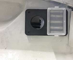
Today I put in the live wire and fuse for the radio. I then stripped the radio housing of its vinyl and drilled a 30mm hole for the twin socket USB charger and voltmeter. The existing foam was crumbling away so I looked at some replacement foam on the internet (as I already had a roll of black vinyl) but although it was cheap the delivery charges were horrendous. In the end I ordered a re-trim kit from Park Lane Classics which came to £9.50 delivered. This includes foam, vinyl etc.
This is how it should look (no vinyl trim yet):

The radio comes from my 1969 Morris Mini Cooper, so it will be right in period! When I sold the car around 1977 I kept the radio. My friend Steve of 'On The Air' has adapted it with a audio socket on the back so I can attach my iPod (although this is now out of date - I now use bluetooth in my modern Honda Civic!).
Tuesday 23rd July 2019
Today managed to insert the wires for the reverse switch, overdrive switch and oil pressure warning light into the fuse box. I had a slight hiccup as the wire for the reverse switch came out of the terminal after insertion into the module. These can't really be removed without a special tool but then, as I have a few unused slots I just re-assigned it (with a new terminal) to another free slot. The fuse box was then screwed into place.
Thursday 25th July 2019
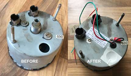
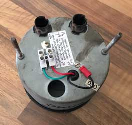
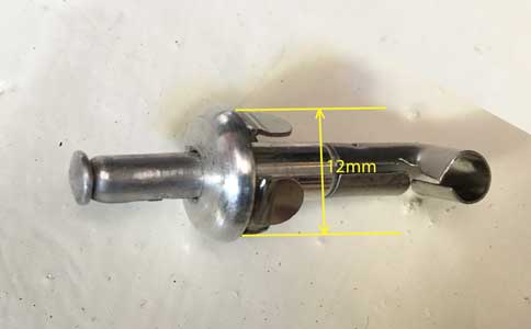
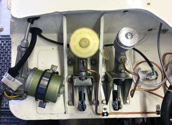
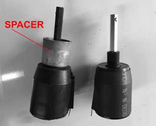
Went to see Dad today, but I did a bit of research as I need to find out why, with a new windscreenwiper motor and switch, the park still doesn't work, I read in a thread somewhere that if the park doesn't work a new switch may be needed, so I bought a shiny new remanufactured one from Moss-Europe. It came with a useful 3 page leaflet with details about it. To see it click here. I may have misinterpreted the thread as the switch referred to may be the switch fitted to the motor itself which contains the terminals to which the plug is attached, and not the dashboard switch so I could have saved myself £50. This other 'switch' contains a spring loaded pin which engages with a cam on the gear assembly to operate the park function. According to the Vintage Triumph Register "With the dash switch off, power is supplied to the motor through the contacts of the parking switch, and the motor continues to operate. Until the drive gear rotates to the point where the cam operates the switch plunger, the motor will operate at the normal, or low speed, just as if the dash switch were still on".
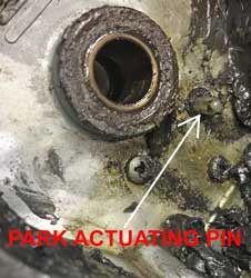
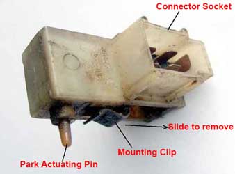
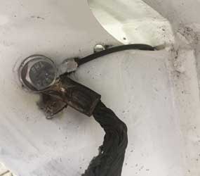
The pin can be seen in the picture above left of the old motor. This protrudes from the 'switch' mounted on the motor as per above right. I'll have to check this is working properly, if not the old dashboard switch was probably ok - if so I can sell it on ebay.
Friday 26th July 2019
Spent nearly all day trying to find out why the park doesn't work on the wipers. To see the circuit click here. Looking at the circuit, the live (green) goes to terminal 4 on the wiper motor. This should be live when the ignition is on and the wiper switch is in the off position and it is, I checked it with a multimeter. When the pin above is protruding i.e. not on the cam of the gear wheel, terminals 2 and 4 are connected. I've checked this with a multimeter and they are! When the switch is off, terminals 1 and 2 are connected so thye live current goes to terminal 5 of the motor and the slow speed is actuated until the cam hits the pin when it parks. However although I've checked terminals 1 and 2 are connected, no current is getting to the Brown wire feeding the slow speed motor connection with the ignition on and the wiper switch in the off position, so parking is not possible. The only credible reason I can think of is that the connector in the motor is not making contact at the green (live) terminal. To check this (having determined that there is 12v at the green terminal) I'll need to check there is voltage at terminal 1 of the windscreen wiper switch.
Saturday 27th July 2019
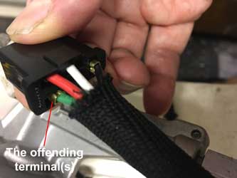
There was no voltage at terminal 1 of the wiper switch, so clearly there were no connections at terminals 2 and 4 at the motor. In the end it was very simple, I just removed the female spade terminals of these 2 terminals from the plug at the motor, turned them around and re-inserted them. They should 'click' in but plainly they didn't.
A lot of time was spent on this problem which ended in a simple solution, as is often the case. However I have learnt a great deal about windscreen wiper systems and have uploaded a page on this. See The GT6/Electrics/Windscreen Wiper System.
Then I connected the pipes for the screen washer. In initial tests it failed to work and the motor nearly died. Removal of the filter at the bottom of the tube in the bottle rectified this and it now works perfectly!
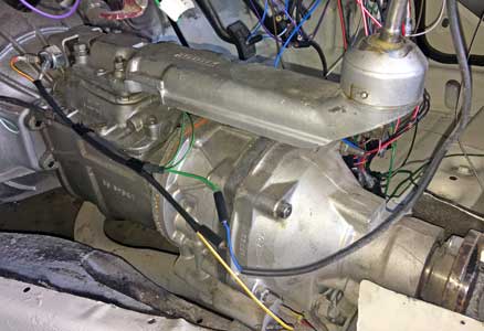
Later I wired in the oil warning light. This was missing before (I fitted an oil pressure gauge) but with a T piece I intend to have both. Then I started tidying the wiring in the front passenger footwell in preparation to removing the gearbox cover to wire in the reversing light and overdrive. This cover was installed temporarily while I did the wiring.
Sunday 28th July 2019
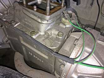
Wired in the reversing light to the switch on the gearbox, after tidying the wires under the dashboard, and removing the gearbox cover and the remote (as the switch is underneath). The wires for this and the live feed for the overdrive were put in a spare black plastic tube for neatness and protection.
Monday 29th July 2019
Today I finished the wiring (apart from some tidying and the instruments). Wired up the overdrive, at the overdrive switch (which ensures overdrive is only selectable in 3rd and 4th gears) and the gear knob, which is GT6 Mk3 style with a switch in the gear knob.
The reversing light works!
Finally did the connections at the gear knob. When the switch is turned on there is a click at the solenoid. The overdrive can't be tested until the car is driven on the road.
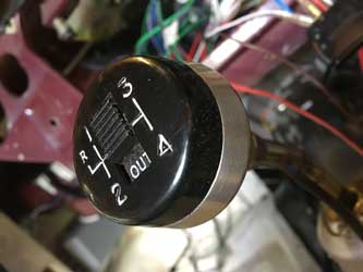
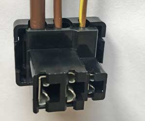
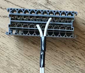
The tiny loom for the gear knob overdrive switch has a strange way of connecting which was not obvious at first glance. The underside of the switch looks below left.
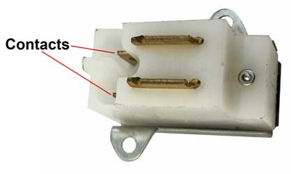
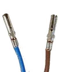
The loom connectors, which are a little unusual, look like above right. The slots slip over the contacts. If they are a little loose close them up with pliers, and if too tight open them up with a thin screwdriver, but they must be a fairly tight fit or they may they will fall out with normal vibration when the car is being used!
Thursday 1st August 2019
Busy with Granddaughter today, but found a little time to tidy up the wiring in the passenger footwell and fit the passengers footrest panel.
Friday 2nd August 2019
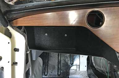
Today fitted a new parcel tray in the L/H passenger foot well, as well as the LHS of the new dashboard. This presented some problems (with the parcel shelf): It wouldn't fit properly by the door, it obscured the new fuse box cover so it couldn't be removed, and the bottom padded rail was missing and they are no longer available! I'll have to put my thinking cap on - all problems are solvable!
Saturday 3rd August 2019
Some problems solved! I had to get the stanley knife to the parcel shelf! A bit of a trim to the left enabled it to fit next to the door aperture, and a small triangular piece was cut from the bottom LHS inside to enable access to the fuses. I may not be able to use the cover as I can't access the top clips - but I'm sure I could improvise something! The only remaining problem is the padded rail. I thought at first I would make one, as I have the LH one to copy. However I initially thought it was straight so I could use some angled aluminium and cover it in black leathercloth. However, like the RHS it is actually slightly curved!
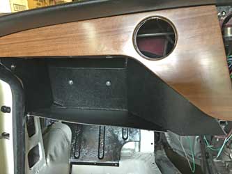
The parcel shelf is now secured with all the correct fasteners in all the correct places and the fuses are all accessible! After some investigation (googling) I find that I could have bought the padded rail from James Paddock when I visited yesterday! According to my parts book the part number is 709692 but they are selling the same item (728631) for £29.95.
I refitted the repainted ash tray and demister nozzles and outlets to the cleaned and "black shoe polished" dashboard top! I used new 10-32 stainless nuts.
I also refurbished the last of the instruments.
Tuesday 6th August 2019
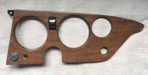
Today I prepared the dashboard. It came from a Mk3 and as it had been reveneered it had lost the 'HAZARD' under the Hazard Warning Light, so I used Letraset to replace it.
Also the RHS didn't have the hole for the ignition (on the Mk3 this was on the steering column) so I had to drill this, together with a recess underneath for the barrel.
I still need to increase slightly the size of the hole for the Hazard Warning Switch between the speedometer and tachometer as it does't fit at present (probably a build up of varnish when lacquered).
Thursday 8th August 2019
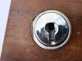
Not much today - just fettled the right hand part of the dashboard to accept the ignition switch and the hazard warning switch. First I used Araldite to build up the hole for the ignition, as it had a flat and needed an appropriately shaped hole to stop it turning with the key.
The aperture for the Hazard Warning Switch just needed a judicious amount of filing to get it to fit. Below the semi-finished item (still needs tacho, speedo, vent, choke cable and windscreen wiper/washer switch).
Friday 9th August 2019
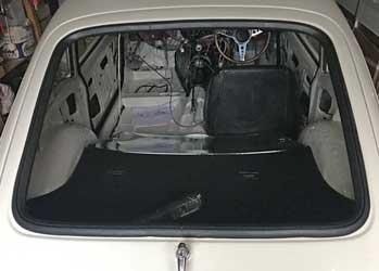
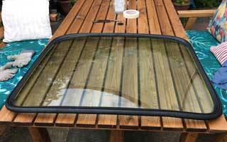
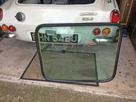
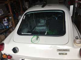
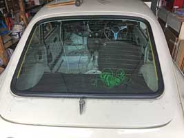
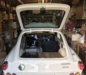
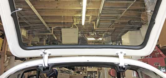
Eureka! Dave Jackson phoned, arrived in 5 minutes and fitted my rear window in around half an hour! Very reasonable too. I noticed that they started at the right hand side where it is probably easier to fit as it is less than the bottom or top. Also they used quite a big rope - like an old fashioned skipping rope. Now I just need to tidy up the HRW wires.
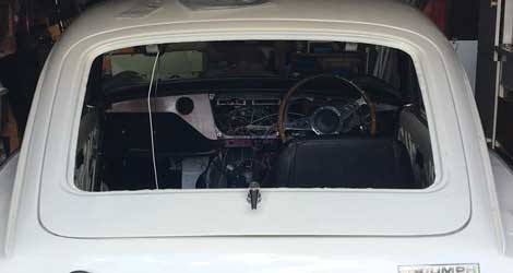
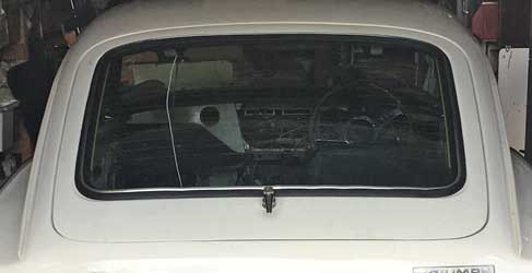
Above: before, just arrived and after fitting.
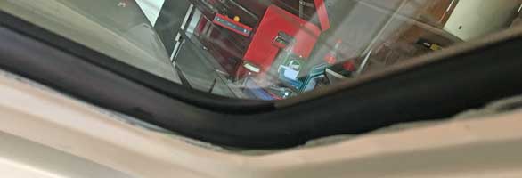
He said that a lot of the aftermarket rubbers are very poor, and in this case not too bad, but the finishing strip was a bit rubbish! Also the groove in the rubber was not sufficiently deep or narrow to grip the strip along the top where the strip is a bit loose. Also the plastic strip itself creased at the corners - Dave said the summer sun would sort that out!
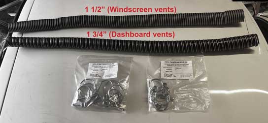
Received the replacement silicone duct hosing for the dashboard and under dash heating/ventilation and windscreen vents as well as the correct wire clips.
Monday 12th August 2019
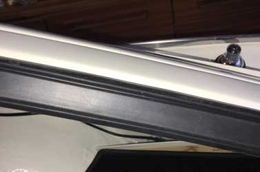
Today I looked more closely at the tailgate - the finishing strip could be better at the corners (perhaps I should get a new one and do it again).
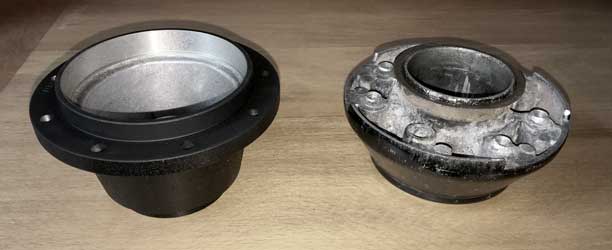
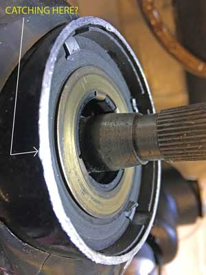
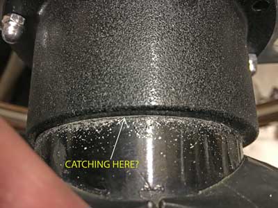
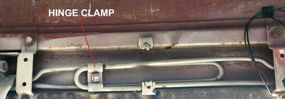
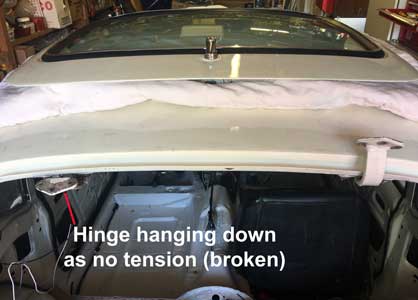
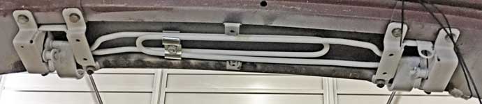
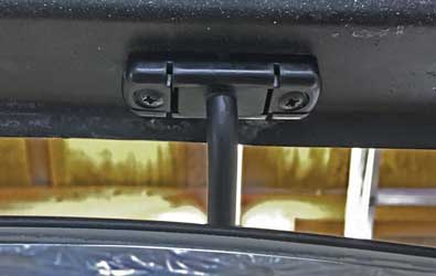
Also there is a problem in that with the increased weight of the glass, the tailgate won't stay open. I initially thought that this was simply a matter of adjustment. The only visible form of adjustment seems to be the hinge clamp seen below.
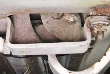
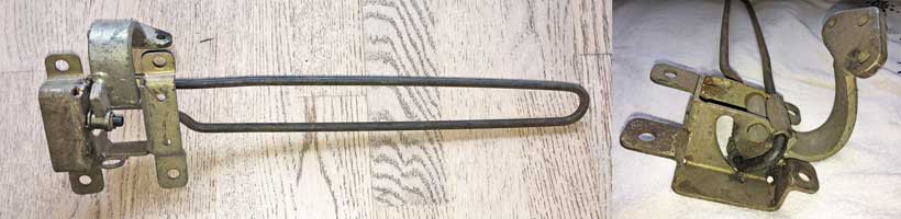
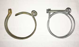
First I looked at a thread on the Club Triumph forum which seemed to indicate that this should be more central, so I moved it. However this made no difference. Looking at the torsion bars, they don't seem to be moving when the tailgate is lifted (I would expect one to turn). I put a mark on the springs with a felt pen and took photos both with the tailgate open and closed and there was no difference with the LH one, the RH one moved slightly. Looking more closely at the springs I came to the conclusion that the LH spring had broken (see below).
Compare this to part of an image of the LH hinge of one on ebay (below). Part of the spring should be in the curved hole and this should move when the tailgate is opened. This seems to be entirely missing on mine.
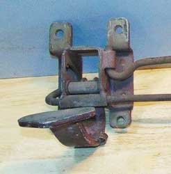
I've come to the conclusion that the LH spring is broken, the RH spring on its own was sufficient to hold the tailgate up with no glass, but not with the glass in. They are listed in the Spare Parts Catalogue as 625608 (LH) and 625609 (RH). However, in the words of TSSC GT6 Register Secretary Andy Cook (whom I emailed on this) "Those springs are very difficult to get hold of, as you mention, Canleys have one side only. In my experience they usually tend to break rather than lose torsion, I had one break on one side quite a few years back". Fortunately the one Canleys have in stock is the LH one so I've ordered it today (£38.75). Fitting will entail removing and refitting the tailgate which I'm not looking forward to but it will have to be done.
As regards the fitting of the ventilation duct piping under the dashboard, I made a start!
I have another problem with the bracket for the lower passenger ventilator, in that part of it is missing (622507). Helpfully GT6 owner Ralf in Germany has sent me a photo which I can use to make a replica. I have the circular bracket which grips the vent, I just need the bracket attaching this to the lower parcel tray support assembly,
Tuesday 13th August 2019
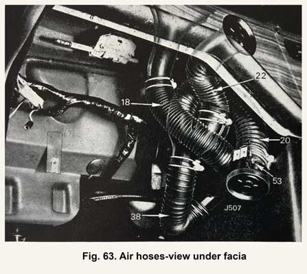
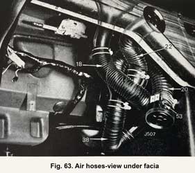
Today I tried to fit the 45mm ducting to the Y piece for the dashboard ventilation and it doesn't fit. Measuring the ID it is around 43mm! Nothing seems to be going right at the moment - very dispiriting! Sent an email to AutoSiliconeHoses to complain but no reponse, I must phone them. I altered the cover for the fusebox as the top catches were not accessible with the parcel shelf in place - it now just 'clicks' on. I've found a bit of stainless steel in the garage to make the bracket, above. I trust the driver side will be a reverse version so I'll make that as well. I reproduce the picture in my workshop manual of the duct arrangement on the passenger's side. The bracket (above, and below item 53) can be seen but of course as it is attached to the parcel tray support, and as this has been clearly removed, this arrangement is not shown.
Wednesday 14th August 2019
New LH tailgate spring arrived from Canleys. It looks a lot different from mine, the curved part of the spring, which seems to be missing from mine, is clearly there.
Had a response from Auto Silicone Hoses. They have offered 51mm as replacement FOC, but why can't they supply 45mm with a I.D. of 45mm, not 43mm. I can't recommend this firm, even though they claim "ASH has become the first choice for, performance specialists, engine tuners, race & rally car preparation teams, commercial vehicle and PSV Operators. Customers include Specialist Vehicle car manufacturers and F1 teams".
Friday 16th August 2019
Received the 51mm ducting from ASH but it was ridiculously large. Its poor when I can't find 45mm ducting which has a true id of 45mm! The 38mm ASH sold me was fine. I've messages somebody from ebay to see if they can guarantee 45mm id on their products. I've solve my problems with the brackets etc for the downward facing vents thanks to my kind friend in Germany who is sending some spare parts he's accumulated. Taking my Dad to hospital again (went yesterday) so no time for work today.
Saturday 17th August 2019
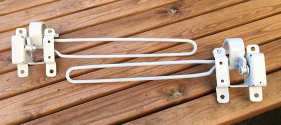
With the help of my long suffering wife I removed the tailgate and, with the car roof protected by an old quilt, placed it there. It was then obvious that the LH spring was not working, but the RH one was.

I unbolted both springs and painted the old RH and new LH springs. I will fit them with new bolts etc. I suspect refitting the tailgate will be a lot harder than removing. Hopefully with the new LH spring from Canley's it will all work properly when re-assembled.
Friday 23rd August 2019
Returned from a few days away to receive the items from my friend in Germany which include the unobtainable brackets 622507 & 622507 and the ring clamp 622136.
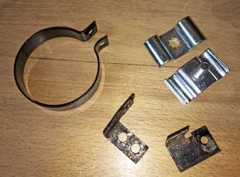
With the chrome plated tailgate spring clamp assembly (above) I am now in a position to refit the springs and replace the tailgate. All the parts can be seen below:
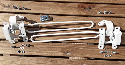
Below, fitted into the car:
And it has cured the problem, the tailgate now stays up.
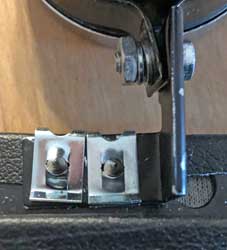
The next job was to assemble the downward facing vents onto the parcel tray supports, now I have the correct brackets. The LH support is new (Spitfire part, but identical). It didn't have any holes for the bracket so I used the old RH support as a template. The No.8 Speed Clips and No.8 x 3/4" panhead self tappers are new and as far as I can ascertain are as originally used. The brackets are from Germany, below is the LH.
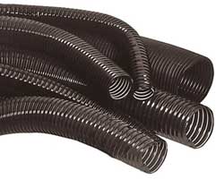
I've also given up on getting some 45mm Silicone ventilation ducting, nearly every other supplier uses ASH (Auto Silicone Hoses) and they appear to be manufactured too small (43mm id). I've therefore ordered some "Lightweight Flexible Plastic Coated Heater Ducting Steel Spiral Wire Re-inforced" in both 1.1/2" and 1.3/4" from Europa Spares. This looks more like the original in any case and they were the only supplier to answer my query regarding size! I'll write off the £30 spent at ASH, or perhaps see if anybody on ebay is interested.
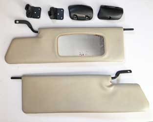
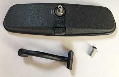
Saturday 24th August 2019
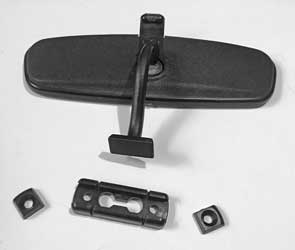
A glorious sunny day (27.5°C) so I did some refurbishment (i.e. cleaning and painting) of the the sunvisor fixings and interior mirror. A couple of items for the mirror mountings are missing (621704 Base & 621705 Retainer), but there seems to be a modern alternative widely available: RTC1006. The mirror iteself is a later dipping variety made by MAGNATEX (TP-RT I 165).
I also connected the Heated Rear Window:
The new L/H spring assembly needs a hole drilling to attach the back door hinge cover (seen in position).
Sunday 25th August 2019
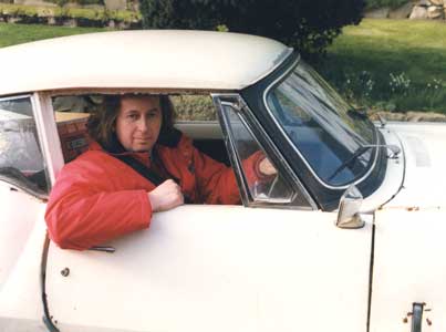
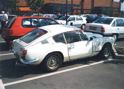
No work today, although I did clean up the rear quarter ventilation vents. Did find a couple of photos taken around the year 1999, one with me in the driving seat (my hair's now shorter), and another with my son (He's now 30)! The car was very much neglected and wheh it later failed its MoT it was taken off the road for 13+ years.
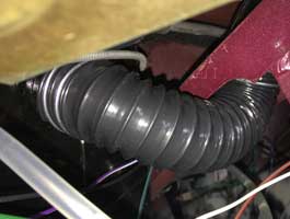
Tuesday 27th August 2019
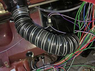
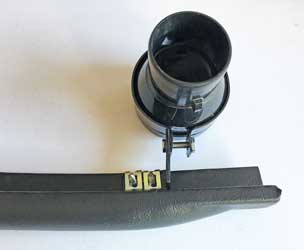
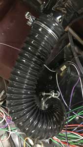
A surprise delivery from Europa Spares of my heater ducting. Looks exactly as the original and, more inportant, it fits!
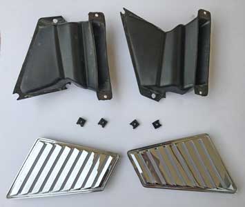
The rear ventilation air extractor ducts were cleaned (the chrome plated outside grills were cleaned on Sunday), and as the spire nuts used (FU2594 - 9/16" x 1/2") seem to be unavailable anywhere (those currently available are rectangular wheras these are almost square) so I cleaned and repainted them!
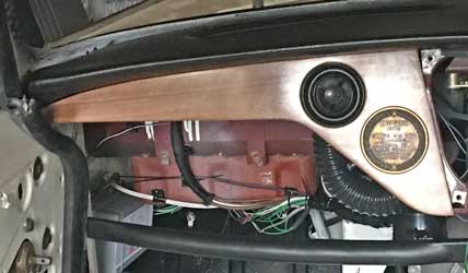
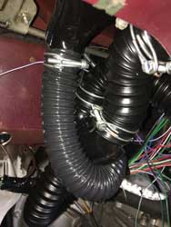
I fitted the new hose to the demister vent, then started fitting the left hand part of the dashboard. Looking at the picture above, I need to tidy up the wires going to the dashboard!
Friday 30th August 2019
Not a lot today, started fitting the dashboard and ventilation ducts to the LHS. Not easy, it's all quite a tight fit! The parcel shelf support is temporily in place, when all the ducts have been installed I'll put in the parcel shelf itself, which has already been slightly modified to fit. I also tidied the wiring a little, binding it in the correct non-adhesive PVC tape. On Wednesday I called at James Paddocks and bought a RTC1006 for the interior mirror. It's an extremely tight fit, I think I'll have to sand a little from the mirror stem to make it fit.
Saturday 31st August 2019
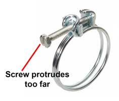
I fitted the ducts as above but the wire clips I bought were very hard to fit, and I took the decision to ditch them, particularly as I did not order enough (from HCL) so I ordered a completely new set from Rimmer Bros comprising 12 - CS4029 (1.3/4") and 4 - CS4024 (1,1/2"). Although this will entail more work replacing those fitted on the left side, I really want it to be right in the end. My original decision to fit new silicone ducts with new wire clips has been an expensive mistake. However I did not know that 45mm ID ducts would be almost impossible to get, and that the clips I bought were unsuitable until I came to fit them. The original ducting had gone stiff in time and was therefore unwise to refit. Also the original clips had corroded, so I think my decision to replace these with new items was correct. Below is the HCL clip (left) and the original (right) which has a greater range making it easier to fit. Also the HCL screw protrudes too far and makes turning difficult.
Tomorrow my son and youngest daughter are treating me to a visit to the Festival of 1000 Classic Cars at Cholmondeley Castle Gardens. I hope to meet one of the youtubers I follow: Ian Seabrook of 'HubNut' fame who is coming in his Reliant Fox.
Sunday 1st September 2019
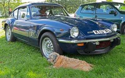
At Cholmondeley I managed to meet Ian Seabrook, albeit very briefly, but I couldn't find his Reliant "Foxanne" (apparantly he had issues with it so came in his CityRover instead). I can highly recommend his youtube channel, to visit it click here. I did manage to photograph a GT6 Mk3 with Cleo, our Border Terrier, sheltering from the sun in front - it was a lovely sunny day.
Tuesday 3rd September 2019
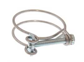
Received the clips from Rimmers - their service and products are really very good! The clips are identical to the original except the screws are slotted-hexagonal instead of slotted-round - so its now possible to get a socket on.
Thursday 5th September 2019
Successfully fitted the interior mirror. All these items will need to come off when I fit the new headlining, but I need to know they will all go on without problems.
I then removed all the heater/ventilation ducts from the LHS and started replacing them. However I was interrupted by a family matter so was unable to proceed!
Friday 6th September 2019
Finally fitted all the ducting on the LHS. Not an easy job, lots of crawling upside down with my head under the dashboard! I used the picture in the workshop manual as a guide:
With the benefit of hindsight, with the LHS I recommend fitting the demister pipe first, but only to the dash top vent. Then fit the ventilation ducting and finally the rest of the demister pipe to the heater. I left the demister duct until last and it was quite hard getting the duct to the dash top vent with the rest in the way. Then I started on the RHS. First I fitted the demister duct from the dash top to the heater. The heater outlet was high up (the LHS was low down) so the pipe run was quite short.
Saturday 7th September 2019
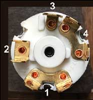
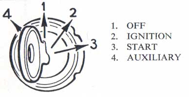
Getting ready to fit the RHS part of the dashboard, I thought about the new ignition (the old one wouldn't fit the GT6 Mk3 dashboard) with it's extra terminal which is live when the key is turned anti-clockwise. The connections are as follows:
| New Ignition | ||||||
| Terminal No. | Colour | Position 0 Off | Position 1 On (CW) | Position 2 Starter (CW) | Position 4 (ACW) | Details |
| 1 | Brown 8.5mm2 (5) | Live feed from battery via solenoid | ||||
| 2 | White 1mm2 (7) | Live feed to ignition warning light | ||||
| White 3mm2 (8) | Live feed to coil | |||||
| White 1mm2 (12) | Live feed to tachometer | |||||
| 3 | White/Red 3mm2 (1) | Live feed to solenoid (starter) | ||||
| 4 | White 3mm2 (10) | Live feed to fusebox bank 1 | ||||
| White 3mm2 (9) | Live feed to fusebox bank 2 | |||||
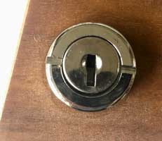
The wiring will be such that when the ignition key is turned to its new position anti-clockwise all circuits are live except ignition related ones i.e. there will be no danger of the coil etc overheating. Below is the back of the ignition showing the terminals.
Tuesday 10th September 2019
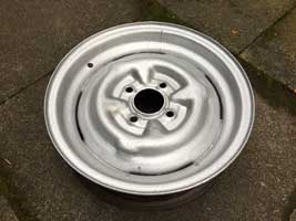
Did a few small jobs today, and as the weather was good, sanded and started painting the (original) spare wheel using some Hammerite gold, left over from another project, as undercoat.
Wednesday 11th September 2019
Finished painting the spare wheel.
Refitted the rear Back Door Hinge Cover and found that there was no hole for the screw on the new spring. I drilled a hole but could not find a self tapping screw to fit. Finally I drilled and tapped both holes in both springs to take a 10-32 pan head setscrew (which needs to be painted black). I then refitted the rear courtesy light and checked it still worked.
Saturday 14th September 2019
I'm not entirely happy with the finish of the painted spare wheel so will take this to Classic & Custom Blasting Services who have quoted £35 to blast and powder coat it. They are in Tarporley which is about half an hour from Chester.
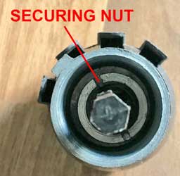
Started with the RHS of the dashboard (with speedometer and tachometer). First, I couldn't find the 1mm2 blue/white wire for the high beam warning light, I'd apparantly forgotten to do it! I therefore broke into the 2mm2 blue/white wire gong from the relay in the fusebox to the headlights with a twin connector (B) and ran a 1mm2 blue/white wire to the RHS of the dashboard. I also connected an earth wire (black) but not yet routed this to an actual earth. The wiper/washer switch was quite tricky as I had to remove the spacer from the old switch and fit it to the new one. This entailed unscrewing the securing nut (which is recessed inside the spacer) and reattaching it to the spacer on the new switch. I did this with a small slotted screwdriver, but getting the thread to engage without cross threading took a few minutes.
Below the RHS of the dashboard with the High Beam warning light connected (extreme left). Note the wiper switch on the extreme right. The tachometer has been converted to electronic.
Monday 16th September 2019
Took the spare wheel to Noel at Classic & Custom, which turned out to be nowhere near Tarporley! The nearest place is probably Bunbury but it is really at the back of a working farmyard 'in the sticks' of Cheshire and was quite hard to find. I also took the carburettor dashpots to be polished up to give the engine a better appearance.
I also continued with the wiring connections to the speedo and tacho.
Tuesday 17th September 2019
My latest acquisition!

Today I made up 4 leads and soldered them to new MES bulb holders for the instrument illumination.
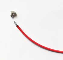
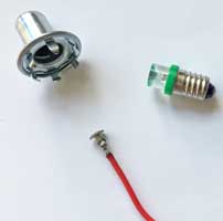
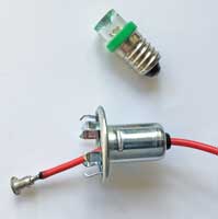
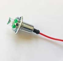
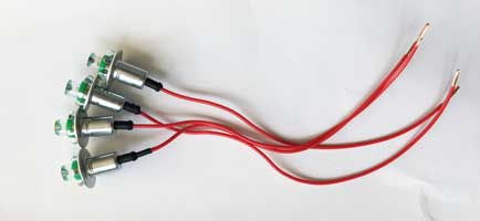
The bulbs are LEDs.
According to my German friend, the star shaped clips which engage with the top part of these bulb holders can separate, and he recommends super-glueing them in place.
Thursday 19th September 2019
When I came to connecting the wires to the new Hazard Switch, I noticed that the terminals are numbered differently. Below is the original switch (left) and the new one (right). I therefore checked them for continuity with a multimeter and found that with the switch 'off', 7 and 8 are connected but not the others. When the switch is 'on' 7 and 8 are not connected but all the others are. This means that 1 and 2 are replaced by 7 and 8, and 5, 6 and 3 are replaced with 1 to 4.
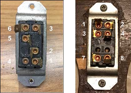
I therefore connected as follows:
| Connections - New Switch | ||
| 1 | To LH flasher lamps | Green/Red |
| 2 | To RH flasher lamps | Green/White |
| 3 | To hazard flasher unit | Light Green/Pink |
| 4 | - | - |
| 5 | ||
| 6 | ||
| 7 | To fuse box | Green |
| 8 | To flasher unit | Green |
Monday 23rd September 2019
Very tired, after a weekend away celebrating my sister-in-law's Birthday (in Derby where 24 of our family were staying in the Midland Hotel).
Eventually, when I got to the garage, I fitted the speedometer drive (from the gearbox) punching a hole in a new rubber grommet at the firewall. Then I fitted the speedometer and associated warning lights and turned on ignition to test. Calamity, the DRLs are flashing!! Something must be connected wrongly as it all worked correctly when I originally did the wiring. Further checks revealed that the new Hazard Switch I bought is completely different inside so there was an aspect of feedback, hence the DRLs flashing! My initial checks at continuity were not rigorous enough. I therefore re-used the old switch (using the new one would necessitate a major revision of my carefully designed circuit). I did strip it down and clean the contacts with some fine emery paper. On re-testing it all now works as it should.
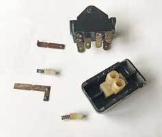
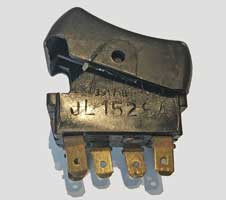
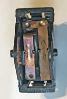
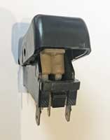
Original connections were as below:
| Connections - Hazard Switch | ||
| 1 | To flasher unit | Green |
| 2 | To Ignition | Green |
| 3 | To RH flasher lamps | Green/White |
| 4 | - | - |
| 5 | To hazard flasher unit | Light Green/Pink |
| 6 | To LH flasher lamps | Green/Red |
The motto is - never assume a replacement is identical to the original! The new one most probably was designed for the more modern Spitfire etc. The downside is the red triangle on the old switch is somewhat faded.
Wednesday 25th September 2019
Making progress! I'm not sure about the clamps holding the tacho and Speedo, as to whether they should engage with the metal of the dashboard or just the wood. I had to bend them slightly to engage with the metal as otherwise nothing seems to be holding the dashboard in place except the fresh air vent and possibly the choke, when fitted.
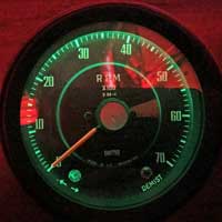
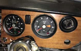
On testing, everything works. Note the green instrument illumination (by LED) which I like.
Thursday 26th September 2019
Got up early and went to Classic & Custom to collect the powder coated spare wheel. Very pleased, I just need to source a tyre. As the wheels are shod with 175/70/13 Dunlop StreetResponse 2 tyres I think I'd like the same tyre with the same profile (70%) but a narrower width of 155 or 165mm so the spare wheel well is not too full. With luck I'll never need to use the spare, but if I do I can drive more carefully taking into account the narrower width on one axle.
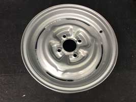
Friday 27th September 2019
Looking online it seems that the instrument clamps are fixed to the wood of the dashboard, not the metal so I will have to pull out the dashboard and refix them - good as I am having trouble accessing them behind the dashboard! These are, I think, part number 620847 and they are also used to clamp the louvre vents at each end of the dashboard (although these arer shorter). They are both pictured below, the shorter one is for the louvre vent and the longer one is for the main instruments. I made a start on this but I haven't felt well today so have deferred the work until I am feeling better!
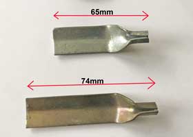
Below is the louvre vent clamping ring 620408, used with the shorter clamp, above.
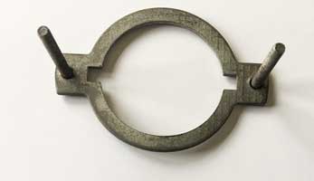
I am missing one of the knurled nuts fixing this (620848) but it is no longer available anywhere, and I can't find the size. The nuts for the instruments are similar (3BA) but not the same. Photographing the thread next to a ruler gives a pitch of approximately 30tpi and the diameter is 4mm (5/32").
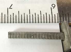
I sent an email to Tim at Grove Components, and he suggested it may be 8-32 UNC, so he is sending me an appropriate nut to try.
Friday 4th October 2019
Arrived back from a few days in the Yorkshire Dales to receive the 8-32 UNC nut from Grove and it fits perfectly! The difference between these and 10-32 / 3/16" threads is that although the TPI (threads per inch) is identical at 32, the "major diameter" is 5/32" instead of 3/16". To my knowledge it's the only time such a small unified thread is used on Triumphs. Smiths who made the instruments used a similar 3BA thread but although the diameter is very similar, the pitch is smaller giving a TPI of 34.8. The instrument knurled nuts go on but then lock on with the pitch being smaller. Why Triumph didn't used this thread for the vent clamping rings, is lost in time!
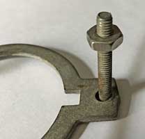
Triumph originally fitted a knurled nut (620848) and I can see why this is no longer available - a quick google search reveals that no 8-32 UNC knurled nuts are available anywhere!
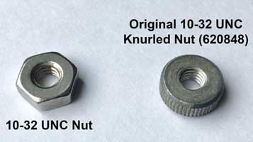
I am not doing any work at present as I have a had a nasty cough for a few days!
Monday 7th October 2019
Did a simple job today - refitted the carburettor dashpots which had been vapour blasted with the spare wheel, with new ECO Hydrin Diaphragms which are supposed to be ethanol proof. The Hydrin diaphragm is on the left (it is lighter in colour).
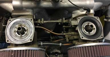
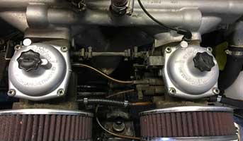
Tuesday 8th October 2019
Did a more difficult job today. When I fitted the driver's side of the dashboard I couldn't get the instrument clamps in place, plus I had refitted them wrongly, clamping the metal rather than the wooden part of the dashboard. To do this again was not easy - I would recommend doing this without the steering column in place as the wooden dashboard needs to be partially out when the instrument clamps are fitted. However I was not prepared to remove or lower the steering column, but eventually I managed it. Below is a picture taken under the dashboard to show how tight things are behind!
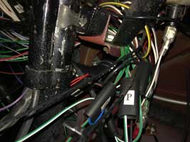
Wednesday 9th October 2019
Fitted the choke cable and the wiper/washer switch. Started the engine. It takes quite a lot of revolutions to start the engine, as if the fuel falls away and needs to be pumped back to the carburettors. Still, its the first time since 20th July, nearly three months. Gratifying to see the tachometer working, since it was converted to electronic (see below left) - ticking over at 500rpm. Once the engine is running it seems to go quite well, as usual. Unfortunately, although I stripped and cleaned the carburettor back in 2012, it's quite dirty again!
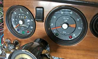
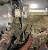
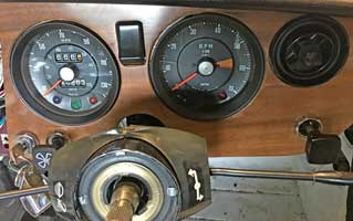
Friday 11th October 2019
Today I had a tyre fitted to the (powder coated) spare wheel, a Dunlop StreetResponse2 as fitted to the other wheels, so they are all Dunlops (as were the originals).
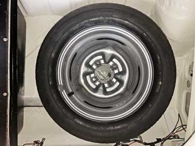
I made a start with the central section of the dashboard. First, I discovered that I'd made an assumption that was wrong. On 17th September I made up four MES (with insulated claws to fit 5/8” dia. panel holes) bulb holders for the illumination for the four instruments. However the middle 2" instruments don't use these - they use BA9s holders, the same as the warning lights. So I had to order 2 more holders from ebay, and I'll need 2 more green bulbs for the illumination from Classic Car LEDs. Below is this part of the dashboard. The new light switch was too loose a fit, and the aperture had to be reduced with masking tape, a bit 'Heath Robinson' I know! Note the electronic voltage regulator for the fuel gauge.
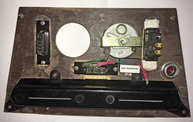
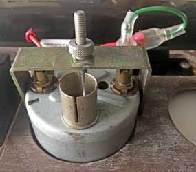
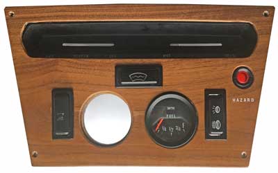
Friday 1st November 2019
After quite a long time with a heavy cold I really didn't feel like working on the car! However today I felt a little better, and it has warmed up to over 14 degrees C, so I opened the garage door and continued with the rear tailgate. I had fitted a rubber seal around the aperture and with this in place the door wouldn't shut. I therefore slackened the 6 nuts holding the tailgate and it shut, although it was a little tight. I then re-tightened the nuts. Hopefully with use it will become easier.
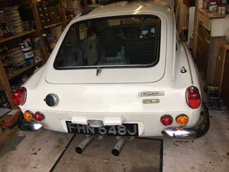
After this I tidied the rear board area and discovered that the screws holding the spare wheel board and the petrol tank board are completely different!
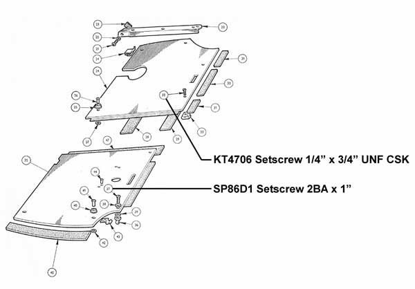
As can be seen above, the 2 petrol tank board screws are 1/4" UNF wheras the 2 spare wheel board screws are 2BA (as far as I can ascertain - I can confirm when the 2BA screws I have ordered arrive). The Standard-Triumph Hardware Catalogue does not list SP68D1 but does list SP86C1 as 2BA, I assume they must be similar (it's dangerous to assume, I know!). Canley Classics list the KT4706 at 35p each wheras the SP86D1 are unobtainable. Of course nobody gives a size!
Tuesday 5th November 2019
First I checked the fuel gauge worked by connecting it to a 9v battery. The electronic voltage stabilizer limits any voltage to 10v so 9v should give a reading of 90% full, which it does (see below). I now know the gauge works, so any problems that occur when I fill the tank (currently nearly empty) will be the fault of the tank float sensor, not the gauge.
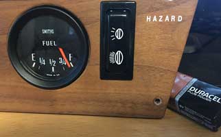
I then started installing the central part of the dashboard, first by connecting the wires for the fuel gauge,
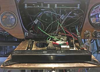
Friday 8th November 2019
I wanted to a bit today as I am feeling much better, but other things prevented me! I did buy a train ticket to Birmingham tomorrow to visit the big Classic Motor Show at the Birmingham NEC. I've arranged to meet the motoring writer Lance Cole who wrote glowingly about the GT6 in his book "The Classic Car Adventure: Driving Through History on the Road to Nostalgia" (see my quotations page).
Saturday 9th November 2019
Went to the Classic Motor Show. The size of this can be illustrated by the fact that not only does it encompass Halls 1 to 5 and 8 (each hall is enormous) but contains 3000 cars and 300 clubs, as well as many trade stands. I spent 4 hours (plus 5 more travelling to and from Birmingham)and only saw a fraction of what is there, but it is quite tiring being on ones feet for so long and I was dressed for a cold day yet it was very warm. I was pleased to meet Lance Cole on the Saab Owners Club stand and we had a good chat. He is urging me to write a book on the GT6 as he is impressed by the breadth of information on this website. I couldn't find any GT6s but on the TSSC stand, celebrating 60 years of the Triumph Herald was a Coupe very similar to one I owned 'back in the day'. The first Herald built by Mitchelotti was a Coupe and in many ways it was a forerunner to the GT6.
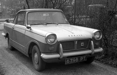
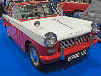
Also I bought a TSSC tax disk holder. Below is my Photoshop recreated tax disk (the car was first taxed on 01/01/1971 so for 12 months ending in December 1971) which will be displayed on the windscreen as when the car was new.
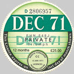
Monday 11th November 2019
Today I connected the wires to the interior light switch in the central part of the dashboard, and tested it - it works. I also received the 2BA screws for the spare tyre board, but at 1" they were too long and wouldn't screw down. I've ordered some 1/2" and 3/4" ones from Spalding Fasteners to try.
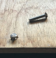
Today I got out the winter car cover from the shed. Unfortunately it had been eaten by mice (see below) so will have to go in the bin. I've ordered a new one from Concours Auto Products, as they are reasonably priced and recommended by Auto Express (see their comments further below).
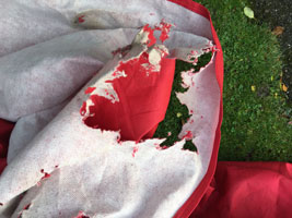

Thursday 14th November 2019
Connected the rest of the wires in the central dashboard and tested (interior light, HRW and lights) and all worked. Finally I need to connect the combined temperature gauge/oil pressure gauge and the instrument lights. As the light was fading and it was raining I fitted the new car cover:
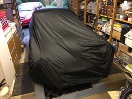
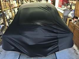
Tuesday 19th November 2019
Apologies - I am in the process of modifying the menu structure of this website - please bear with me!
Monday 25th November 2019
I've just finished installing the new Menu structure. I hope everything works OK!
Tuesday 24th December 2019


![]()