Differential
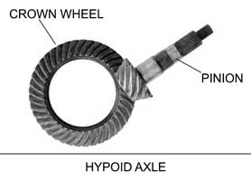
The differential is the internal part of the rear axle. It transmits power from the engine, via the propshaft, to the rear wheels. It does this by the use of two gears which engage at right angles to each other so that the engine connected propshaft transmits power to the rear wheels which are at right angles to it. This type of arrangement is called a Hypoid-Bevel rear Axle, the 'Oxford' Dictionary of 'Hypoid' being "A bevel wheel with teeth engaging with a spiral pinion mounted at right angles to the wheel's axis, used to connect non-intersecting shafts in vehicle transmissions and other mechanisms". The teeth are not straight cut (i.e. at right angles to the circumference), they are at an angle or bevel, this enables them to take a bigger load, and they are quieter. In the picture below the propshaft is in red, and the rear axle in green. Either side of the axle can be seen the driveshafts (transmitting power to the rear wheels).
![]()
The two gears are known as the Crown Wheel and Pinion. The Crown Wheel is much bigger because the Pinion (to which the propshaft is connected) is turning much faster than is desirable for the rear wheels, so for one turn of the Pinion thare is only a part turn for the Crown Wheel which drives the rear wheels. This difference in size, measured in the number of teeth determines the ratio between the input speed and output speed (usually expressed in 'turns'). For example if the Crown Wheel has 35 teeth and the Pinion has 9 teeth, then the Pinion turns 35/9 times for one turn of the crownwheel. 35/9 = 3.89. Because they are engineered together, Crown Wheels and Pinions come in pairs, so if a ratio change is desired both these gears must be replaced as a set.
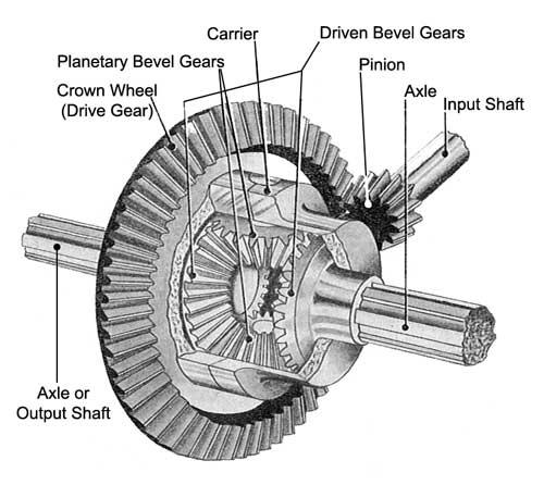
However if the Crown Wheel was directly connected to the rear wheels, there would be a problem when going around a corner, because then the rear wheels need to turn at different rates. This is where the differential comes in, this is a mechanism to allow this to happen. The principle components are shown below:-
The GT6 axle is derived from the one designed for the Standard Eight back in 1953. It was usually supplied with a 3.27:1 differential except when it has an overdrive, when it is was fitted with a 3.89:1 differential. With a 3.27:1 differential a GT6 engine is rotating at 3,404 rpm when travelling at 70 mph in top gear. In overdrive top (with a 20% overdrive) reduces the engine speed to 3,404 x 80% = 2,723 rpm at the same miles per hour. By increasing the differential ratio to 3.89:1 this is increased to 3,240 rpm. This increases torque and therefore acceleration which is what Standard-Triumph intended.
Triumph fitted four different types of Differential:-
| TYPES | Front Pinion Flange | Bolt Holes |
Casing Number Prefixes |
Vehicles Fitted | |
| Front Flange | Output Flange | ||||
| Type A | Square | 5/16" | 5/16" | G,Y, GA & FC | Herald (except 13/60) Spitfire Mk1-3 |
| Type B | Square | 5/16" | 5/16" | GE & FC | Herald 13/60 |
| Type C | Square | 5/16" | 3/8" | HB | Vitesse 6 |
| Type D | Round | 3/8" | 3/8" | FH, FK, FR, FD, HC, KC, & KD. | Vitesse 2 litre; All GT6 Spitfire Mk4 & 1500 |
Type D (which is fitted to the GT6) is considered to be the best, as it has the strongest carrier.
In my particular GT6 I have a 3.27:1 differential fitted with a 25% overdrive. This means that in overdrive top, travelling at 70 mph, my engine is only turning over at 2,553 rpm giving a quiter and more economical experience!
![]()