1. THE ENGINE
The Standard-Triumph cylinder engine was originally developed for the Standard Vanguard Luxury Six, which came out in 1960, see advert below:
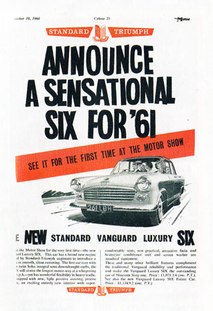
Sir John Black wanted an engine to compete with the Ford Zephr/Zodiac and Vauxhall Cresta which were fitted with an inline six-cylinder engine (I6). The advantages of an I6 engine is that it is inherently balanced - to Quote Car Throttle "Due to the normal firing order of a straight-six, the pistons move in-tandem with their mirror image on the other side of the engine block. So pistons 1 and 6 reciprocate, followed by 2 and 5 and finishing with 3 and 4. As pistons 1 and 6 reach top dead Centre, the other four pistons are evenly spaced at 120 degrees and 240 degrees respectively around the engine cycle, meaning that the reciprocating forces balance each other out. This makes a smooth-revving engine". The engine was a conventional 2 litre design with overhead valves, a cast-iron block and cylinder head, and a pressed-steel sump.The camshaft drove the distributor and oil pump through a spur gear, which was itself chain-driven off the nose of the crankshaft, with the drive covered by a pressed-steel cover. The 2.5 versions had duplex chains.
Beginnings: The SC four
The story of this engine starts with the Standard Eight of 1953 for which an entirely new 4-cylinder engine, known as the SC (small car) was designed by David Eley. Although new, the engine block had to be machined with tooling purchased for the Triumph Mayflower engine so the cylinder centre dimensions of the new 803cc engine were shared with the Mayflower's side valve 1247cc unit. This new in-line engine had overhead valves operated by push rods with the camshaft in the block, with both the cylinder block and head made of cast iron.
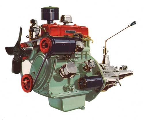
Both manifolds (inlet and exhaust) are on the same side of the cylinder head,
known as a reverse-flow design. Engines with manifolds on different sides are
called cross-flow. As the manifolds are on the right hand side of the SC engine,
the distributor, camshaft, spark plugs and oil filter are on the left-hand side, differentiating it from the similar capacity "A" series engine with which it is sometimes compared; they share the same bore and stroke (58 x 76mm) giving 803cc. The water pump is a separate casting mounted on the front of the cylinder head, indicating that the original 4 cylinder block may have been based on an earlier sidevalve engine with thermo-syphon cooling! The SC engine can be seen below (from a period brochure) :
The I6
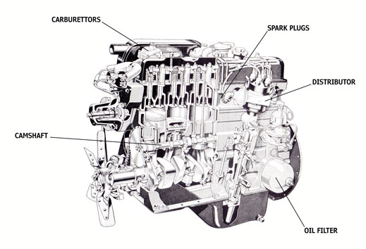
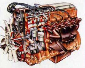
Although the 6 cylinder engine was based on the 4 cylinder, David Eley, who was responsible for both, says that it "wasn't just a six-cylinder version of the SC" and talk of finding the seam where the additional cylinders were added is wrong! It was not even manufactured in the same factory, being cast at Bean Industries (pictured below) which Standard-Triumph had acquired in 1956 (it's history goes back to the 'Bean' motor-car, click here to find out more). According to the Wolverhampton History & Heritage website, Beans produced engine castings for Triumph made from "Bilchrome", a special cylinder iron developed in-house. However the new engine did share the location of the ports, distributor and camshaft, and had similar front and rear block faces to the 4-cylinder SC version. Below is a cut-away of the 2 litre engine, showing the position of the main components. Also the cylinders were siamesed i.e. cast with no water jacket between
each pair, this was done so the engine would be short enough to fit into the Standard Vanguard 6. This also later helped when fitting the unit to small cars like the GT6 and Vitesse. However this also meant that there wasn't room to increase the capacity by enlarging the bores, the only way to do this was by increasing the stroke (see table below).
Although the cylinder head of the original I6 engine had individual inlet and exhaust ports from the start (unlike the SC engine), the breathing was not as efficient as it could be, this came with the inproved head design which came out in the mid to late 1960s as fitted to the GT6 Mk2 and TR5. This was known as the "full-width" head and looked very different to the earlier head (see Engine Modifications).
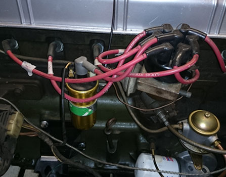
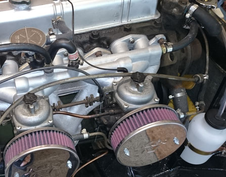
The original carburettors fitted were a Solex, which was not entirely successful (cold starting problems). Although SU carburettors were better, as they were made by competitor BMC, they couldn't be used. A similar variable choke carburettor had to be developed, and this was successfully done by Dennis Barbet of Alford & Alder (a wholly owned subsidiary of S-T). This new carburettor, which had rubber diaphragms, eventually became the Zenith Stromberg CD which was fitted to all the subsequent versions of the six-cylinder engine (until BMC became part of British Leyland, owners of Triumph). Strombergs can be seen in the picture below of the RHS of the engine. They were more efficient than SUs on tickover too. Another picture below shows the LHS of the engine showing from left to right the alternator, coil, distributor, mechanical petrol pump and below that the oil filter.
In 1956 Beans Industries were taken over by Standard-Triumph to produce castings, including cylinder blocks made from 'Bilchrome', a special iron made in-house. The foundry can be seen below, where the I6 engine and cylinder head were cast.

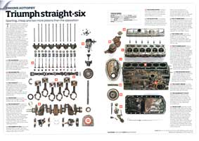
Engine 'Autopsy'
To see this at full size click on the picture below:
To see how I rebuilt my 2.5 litre engine click here. To see a video with Fuzz Townshend (Car SOS) and Mark Field (Jigsaw) rebuilding a GT6 engine click here.
| Various incarnations of the Standard-Triumph 6 cylinder engine | ||||
| Year | Bore & Stroke | Capacity | Power | Car model |
| 1962 | 66.8 x 76mm | 1596cc | 70bhp | Triumph Vitesse 6 |
| 1960 | 74.7 x 76mm | 1998cc | 80bhp | Standard Vanguard 6 |
| 1966 | 74.7 x 76mm | 1998cc | 95bhp | Triumph Vitesse 2 Litre |
| 1966 | 74.7 x 76mm | 1998cc | 95bhp | Triumph GT6 |
| 1963 | 74.7 x 76mm | 1998cc | 90bhp | Triumph 2000 Mk1 |
| 1969 | 74.7 x 76mm | 1998cc | - | Triumph 2000 Mk2 |
| 1967 | 74.7 x 95mm | 2498cc | 150bhp | Triumph TR5 |
| 1968 | 74.7 x 95mm | 2498cc | 80bhp | Triumph TR6 |
| 1968 | 74.7 x 76mm | 1998cc | 105bhp | Triumph GT6 Mk2 |
| 1968 | 74.7 x 95mm | 2498cc | 80bhp | Triumph 2.5PI Mk1 |
| 1969 | 74.7 x 95mm | 2498cc | 80bhp | Triumph 2.5PI Mk2 |
| 1970 | 74.7 x 76mm | 1998cc | 95bhp | Triumph GT6 Mk3 |
| 1976 | 74.7 x 95mm | 2498cc | 80bhp | Triumph 2500 Mk2 |
The
Legacy - The new PE166 Six of 1977
When Triumph engineer Mike Loasby (who
previously worked for Aston Martin) designed the successor to David Eley's Six
(see below) to fit in the new Rover SD1, elements of the original Triumph block were retained to allow continued use of existing casting and machining equipment, just as had previously been done with the original SC engine. Also cast by Bean Industries, the block was lengthened by 20mm, the bore and stroke dimensions of 81mm and 76mm/84mm were retained, and water passages were introduced between the cylinders
(eliminating the siamezed bores).
According to Robert Leitch on the AROnline website "Although it has received a
bit rap in the trade thanks to its well-documented problems, the SD1 Six is a
very capable engine. However, it could have been so much more had it been given
the start it so richly deserved". Now somebody needs to build up a GT6 (Mk IV?)
with this engine, which even in it's prototype stage could put out 150 bhp! To
see the AROnline article click
here.
See a Standard-Triumph - 6 cylinder Engine Animation by Williams Illustration
Click on the image above to see in youtube (the animation is fantastic!)
2. THE CYLINDER HEAD
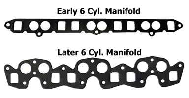
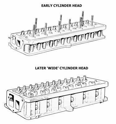
Triumph made various types of cylinder head. They can be identified by two numbers, one actually cast into the cast iron head, and the other stamped (like an engine number). The early Triumph 6 cylinder engines (including the GT6 Mk1) had a completely different cylinder head to later models. It is easily identified by the all the ports being inline, wheras the later "wide" cylinder head did not. This is best illustrated by looking at the manifold gaskets, below:
Another difference is that the earlier heads had distinguishable pushrod tubes visible between the spark plug holes:
According to the official workshop manual
3. THE DISTRIBUTOR
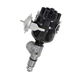
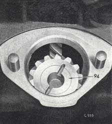
Ignition on the GT6 is by a Delco-Remy D200 distributor (see below left), driven by a bevelled gear that meshes with a similar one on the camshaft (see below right). Delco stands for 'Dayton Engineering Laboratories Co.' and they were pioneers in battery ignition back in 1909. Remy was another American manufacturer of electrical equipment, both became a single division of GM in 1918 known as Delco-Remy. Triumph fitted Delco-Remy distributors to Spitfires and GT6s, probably with their predominant American market in mind. Other Triumphs were fitted with Lucas distributors, which, according to Martin Jay of Distributor Doctor are better quality.
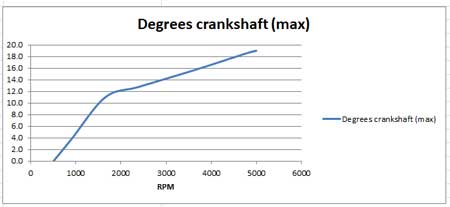
Ignition is "timed" to occur just before the piston in cylinder 1 (nearest the front of the engine). According to Wikipedia "the need for advancing (or retarding) the timing of the spark is because fuel does not completely burn the instant the spark fires, the combustion gases take a period of time to expand and the angular or rotational speed of the engine can lengthen or shorten the time frame in which the burning and expansion should occur. In a vast majority of cases, the angle will be described as a certain angle advanced before top dead center (BTDC)". Static timing for the Triumph 6 cylinder engines should be 10 degs. BTDC. Dynamic timing (controlled by centrifugal weights within the distributor) should be as the table below (with the curve further below):
|
Ignition Distributor - Centrifugal Advance (GT6 2 litre engine) |
|
| RPM | Degrees Crankshaft (max) |
| 500 | 0.0 |
| 900 | 3.8 |
| 1650 | 11.0 |
| 2400 | 12.8 |
| 3600 | 15.6 |
| 4800 | 18.6 |
| 5000 | 19.0 |
4. THE COIL
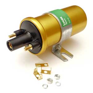
A coil, which acts as a step-up transformer, provides the high voltage (around 40,000 volts) needed by the spark plugs to ignite the mixture in the engine. Coils have two 'windings' around a common core, the primary which is connected to a 12v supply (the battery) and the secondary which outputs the high voltage for the spark at the plugs.
The normal coil fitted to the GT6 is a Lucas HA12. HA refers to High Performance (Standard is LA, BA is an older coding for coils used with a ballast resistor & SA is Sports). The currently available equivalent is known as a DLB105 which has a primary resistance of 3 ohms to suit non ballast resisted ignition.
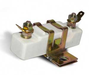
Ballast resisted ignition systems were developed (by Ford in around 1970) to overcome problems with poor cold starting. As the starter takes nearly all the current to turn over the cold engine, it starves the coil of the current needed to provide a nice spark. A ballast resisted coil will have fewer turns so will have a DC resistance of 1.5 ohms instead of the usual 3 ohms. It will give a good spark with only a 9 volts supply. The coil will need two wires or feeds connected to the +ve terminal, one from the ignition which goes through the ballast resistor to give a constant 9v when the engine is running, and one from the solenoid activated by the starter switch giving the full 12v which in a coil rated at 9v provides a 'supercharged' spark to the plugs during starting. The Lucas ballast resistor fitted to the GT6 Mk3 is shown below:
It is critical, therefore, that a 1.5 ohm coil is fitted with a ballast resisted ignition and a 3 ohm coil to a non ballast resisted ignition! Generally the various GT6 models were as the table below (as per the official workshop manual):
| Model | Coil Manufacturer | Type | Primary Winding Resistance | Ballast Resistor Type |
| GT6 Mk1 | Lucas | HA12 | 3.0 to 3.5 Ω | Not fitted |
| GT6 Mk2 | Lucas | HA12 | 3.0 to 3.5 Ω | Not fitted |
| GT6 Plus | Lucas | HA12 | 3.0 to 3.5 Ω | Not fitted |
| GT6 Mk3 (early) | Lucas | 16C6 | 1.43 to 1.58 Ω | Lucas 3BR |
| GT6 Mk3 (late) | Lucas | 2400 | 1.3 to 1.5 Ω | Wire |
As can be seen above, the ballast resistor was introduced in the October 1970 GT6 Mk3. Later GT6s had a resisted wire instead. A section of the GT6 Mk3 Wiring Diagram can be seen below:
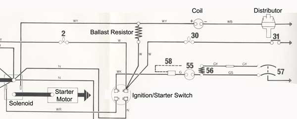
The wire from the ballast resistor to the Solenoid is WY (White/Yellow).
A table showing the values for non-ballast resisted and ballast resisted ignitions is shown below. The nominal voltage given by a 12v battery is 12.6v which gives 52.9 watts power to the ignition with non-ballast resisted ignition (1st row). When ballast resisted ignition is in starting mode (i.e. the ballast resistor is bypassed, 2nd row) a power of 48.2 watts to the ignition is given, even when the voltage drops to 8.5v as can happen when a large proportion of current goes to the starter motor, as when the engine is cold. After the car has started (3rd row) the ballast resistor kicks in to increase the total resistance to 3 ohms, which gives 52.9 watts power to the ignition. With a 1.5 ohm coil but without the ballast resistor (4th row), the power would be double, around 105 watts, which would burn out the ignition, hence the need for a 1.5 ohm ballast resistor with a 1.5 ohm coil! Incidentally later cars didn't have the ballast resistor as shown above, instead they had a 1.5 ohm wire which had the same effect.
| Coil | Coil Resistance | Ballast Resistor | Total Resistance | Amperage | Volts | Power (watts) |
| For non-ballasted ignition | 3.0 ohms | Not fitted | 3.0 ohms | 4.2 | 12.6 | 52.9 |
| For ballasted ignition (starting mode) | 1.5 ohms | Not fitted | 1.5 ohms | 5.7 | 8.5 | 48.2 |
| For ballasted ignition (running mode) | 1.5 ohms | 1.5 ohms | 3.0 ohms | 4.2 | 12.6 | 52.9 |
| Car running with 1.5 ohm coil, but no ballast resistor | 1.5 ohms | Not fitted | 1.5 ohms | 8.4 | 12.6 | 105.8 |
To watch a very clear explanation of ballast resistors on YouTube, courtesy of Moss Motoring, click here.
5. THE SPARK PLUGS
The spark plugs normally fitted are the trusty Champion N9Ys. Albert Champion was a Frenchman who immigrated to the United States in 1889 to race bicycles and motorcycles. He also set up a side business, manufacturing and selling spark plugs in Boston, Massachusetts, as a means of income. William Durant, the founder of General Motors in the USA, spotted Champion’s potential and moved him and his operation to Flint, Michigan, in 1904. The Champion Ignition Company was formed. Over the next few years, Champion lost control of the company, he left and subsequently setup the AC spark plug company in 1908. GM’s production of motor vehicles grew significantly and GM Corp purchased the AC spark plug company in 1909 to service their ever increasing needs. Champion spark plugs used to be made in Upton in the Wirral until the factory closed in 2006. They are now made in Italy.
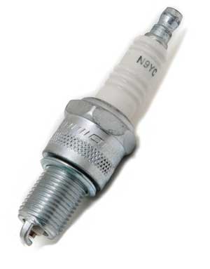
The N9Y has a 19mm reach, a M4 thread and is 14mm in diameter. The single electrode is made from standand nickel.
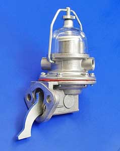
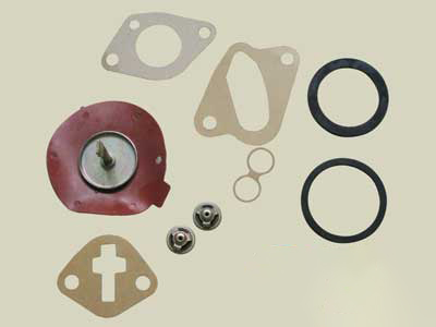
6. THE FUEL PUMP
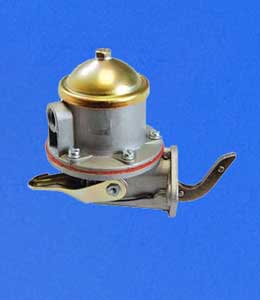
One of the most common type of fuel pumps used in automobiles was the single action, diaphragm-type mechanical pump (before the advent of modern electronic fuel injection). A diaphragm type fuel pump is usually mounted on the engine and is operated by an eccentric lobe on the camshaft. The GT6 is fitted with 2 different types of fuel pump, originally made by AC, the division of General Motors originally founded by Albert Champion of spark plug fame (see above). The GT6 Mk1 was fitted with the version with a glass sediment bowl, as were many Fords of the 50s and 60s, as per the first picture below. This didn't contain a filter (fitting a separate filter is recommended) but at least one could see if there was any sediment! Later models of GT6 were fitted with the brass top version, as per the second picture below.
The AC fuel pump is shown in more detail below:
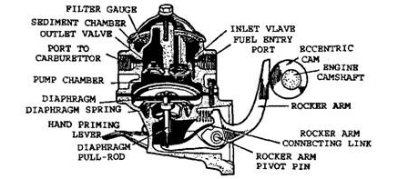
I don't think the current replacement pumps are any longer made by AC, but probably by a manufacturer in the Far East. Repair kits for the originals are available. The one below is sold by ANG but others are, of course, widely available. I have no personal experience of these, but a 'new' pump I obtained from James Paddock did leak when the car was on a slope, but this was cured by fitting the fibre washer they subsequently sent me, under the top locating screw.
7. COOLING SYSTEM
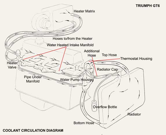
Looking at the diagram above (from Triumph's official Workshop Manual) there are five rubber hoses. The largest are the top and bottom radiator hoses and there is an additional hose from the thermostat housing to the radiator (below the filler) to prevent air locks when filling. The other two hoses run to and from the heater matrix (situated under the dashboard) from the heater valve. A small pipe runs from the radiator cap to an overflow bottle which is attached at the side of the radiator. When the thermostat is closed the water flows from the water pump housing into the water passages in the cylinder head through which it goes into the engine block. Water also flows through the heated inlet manifold. It returns to the water pump through other passages in the cylinder head. When the heater valve is open it circulates through the heater matrix and returns through an additional pipe located under the manifold. When the thermostat opens the water also circulates through the radiator, in at the top hose and out through the bottom hose. A useful description of cooling systems per se can be seen on the CarParts.com website by clicking here.
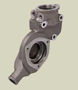
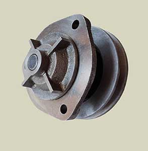
Below is the cast iron water pump housing, and the impellor type water pump. The blades of the 'impellor' can be clearly seen - driven by the engine mounted fan belt these spin causing the water to circulated in the direction of spin.
8. THE CAMSHAFT
There are a variety of camshafts fitted to the Triumph Six Cylinder Engines, usually identified by their (Stanpart) Part Number.
| TRIUMPH SIX CYLINDER ENGINES - CAMSHAFT APPLICATIONS CHART | |||||||
| Camshaft Part No. | Ring ID | Timing ** | Camshaft Lift | ||||
| Applications | IO | IC | EO | EC | |||
| Vitesse & GT6 Mk1; 2000 Mk1 | 306632 | None | 18° | 58° | 58° | 18° | 0.220" |
| TR5 & early TR6 CP**** | 307689 | 2 slim | 35° | 65° | 65° | 35° | 0.250" |
| 2.5 PI Mk1 & Mk2 to MG50000; Vitesse & GT6 Mk2 | 308778 | 1 wide | 25° | 65° | 65° | 25° | 0.232" |
| 2.5PI Mk2 MG50001 to MG75000 | 308778 | 1 wide | 25° | 65° | 65° | 25° | 0.232" |
| 2500TC & S MM20001 on 2000 TC ML1 on; Mk3 GT6 | 307621 | 1 slim | 10° | 50° | 50° | 10° | 0.215" |
| Mk2 PI from MG75001; TR6 CR**** 2500 TC 1974 MM1 – MM20000 | 311399 | 3 slim | 18° | 58° | 58° | 18° | 0.240" |
| Mk2 2000 to ME50000 | 306785 | None | 18° | 58° | 58° | 18° | 0.220" |
| Mk2 2000 from ME50001 | 306785 | None | 18° | 58° | 58° | 18° | 0.220" |
| Source: Chris Witor et al | |||||||
The Ring ID refers to the number of rings in the front journal of the camshaft, useful as an additional identification method.
** The timing angles are as follows:
| 1 | IO - Inlet valve open in degrees crankshaft, B TDC (before top dead centre). | ||
| 2 | IC - Inlet valve closed in degrees crank, A BDC (after bottom dead centre). | ||
| 3 | EO - Exhaust valve open in deg. crank, B BDC (before BDC) - usually the same as IC. | ||
| 4 | EC - Exhaust valve closed in deg. crank, A TDC (after TDC) - usually the same as IO. | ||
TDC is Top Dead Centre, BDC is Bottom Dead Centre. The timing can be illustrated by the following diagram which refers to Camshaft Part No. 306632 fitted to the GT6 Mk1.
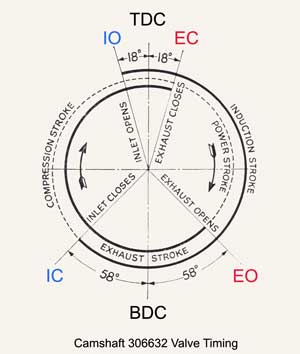
In these cases IO and EC are the same, as are IC and EO (the above would be described as an 18°/58° camshaft). IO/EC and IC/EO only differ in the more 'extreme' camshafts, as for example the ISKY road & race camshaft where the IO is 24° and the EC 1 degree more at 25°.
![]()