
Wiring Loom
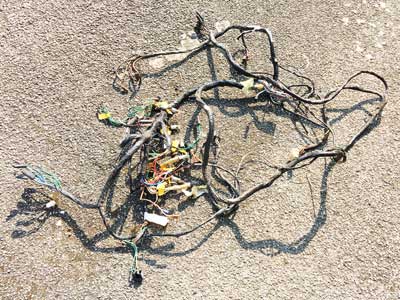
The wiring of my GT6 was pretty shot, so I decided to renew it all. In the end this probably turned our more expensive than buying a new wiring loom from Autosparks (especially when taking into account the investment in tools), but had some key advantages: I could customise it, and get satisfaction from doing it myself, in fact it became a challenge I set myself! Rather than make an actual 'loom' I decided to just fit cables, circuit by circuit. After testing each circuit I bound the cables in Easy Loom™, where needed. This is made by Design Engineering in Ohio, USA. You can visit their website by clicking here. Details from their website appear below.
Easy Loom™ Split Sleeves
Protective
Easy Loom offers a clean, classy way to protect exposed wires, cables
and hoses on trucks, SUV's and powersport vehicles including ATVs and
UTVs. Superior in style and function to simple plastic tubing, DEI's
Easy Loom adds a superior level of protection to sensitive wires cables
and hoses exposed to abrasion or the elements; all with a clean, classy
look.
• Protects against abrasion,
chemicals & the elements.
• Clean, classy way to protect
wires, hoses & cables.
• Superior style & function vs.
plastic tubing.
• Split design makes installation
easy.
• No need to disconnect wires.
• Available in multiple
diameters.
Radiant Heat Resistance:
347°F
Melting Point:
500°F
You can get Easy Loom™ from ebay (limited sizes available) or Demon Tweeks.
I ripped out the entire loom, except from the heavy duty connections to the battery, which were replaced fairly recently.
First I had to make some basic decisions:-
• What type of cable to use.
• What type of connectors to use.
• How to fuse the circuits.
• Whether to introduce more relays.
Two types of cable are available for this application, original single core PVC and thin wall single core PVC cable. According to Vehicle Wiring Products in Ilkeston, Derbyshire, from whom I bought all my supplies, thin wall single core PVC cable is "a high performance cable which as the name suggests has thinner insulation. It is multi-stranded copper cable which is insulated with thinner hard grade PVC which offers good resistance to abrasion and cut through. The cable also carries a higher load compared to the standard auto cable. Gives savings in weight and volume when used in large harnesses. This cable is now original equipment on most new vehicles". I decided to go with this, as it would make the loom smaller (in diameter) make it easier to get mutiple cables through tight spaces and take less room generally. Below is a table of the available single core PVC cables with detailed specifications:
| SINGLE CORE PVC THIN WALL CABLE | |||||||||
| Ref | No. of strands | Strand dia (mm) | Strand area (mm2) | Total area (mm2) | Cable ID (mm) | Cable OD (mm) | Wall thickness (mm) | Max Load (amps) | Typical Applications |
| 16/0.20/0.5 | 16 | 0.20 | 0.03 | 0.50 | 0.80 | 1.60 | 0.40 | 11 | Side & tail lights, alarms, reversing & rear fog lamps, electric aerial, horns, general wiring. |
| 32/0.20/1 | 32 | 0.20 | 0.03 | 1.01 | 1.13 | 2.00 | 0.43 | 16.5 |
Side & tail lights, alarms, reversing & rear
fog lamps, electric aerial, horns, general wiring. |
| 28/0.30/2 | 28 | 0.30 | 0.07 | 1.98 | 1.59 | 2.70 | 0.56 | 25 | Headlamps, fog and driving lamps, rear/front screen heater, wiper motors. |
| 44/0.30/3 | 44 | 0.30 | 0.07 | 3.11 | 1.99 | 3.30 | 0.66 | 33 | Charging cable for battery feed & ammeter. |
| 56/0.30/4 | 56 | 0.30 | 0.07 | 3.96 | 2.24 | 3.70 | 0.73 | 39 | Charging cable for battery feed & ammeter. |
| 84/0.30/6 | 84 | 0.30 | 0.07 | 5.94 | 2.75 | 4.30 | 0.78 | 50 | Charging cable for dynamo, alternator and ammeter circuits. |
| 97/0.30/7 | 97 | 0.30 | 0.07 | 6.86 | 2.95 | 5.00 | 1.02 | 57 | Charging cable for heavy duty alternator and ammeter circuits. |
| 120/0.30/8.5 | 120 | 0.30 | 0.07 | 8.48 | 3.29 | 5.50 | 1.11 | 63 | Charging cable for heavy duty alternator and ammeter circuits. |
| 80/0.40/10 | 80 | 0.40 | 0.13 | 10.05 | 3.58 | 6.50 | 1.46 | 70 | Charging cable for heavy duty alternator and ammeter circuits. |
I decided not to use the popular coloured insulated terminals, as they are less secure, and I believe the factory used non-insulated terminals.
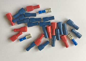

This meant buying a set of crimping and other tools which were not cheap, but the end result should look more professional! To see the tools I used click here.
The original GT6 fusebox had 3 glass fuses, all rated at 35 amps. I decided to keep, particularly as the loom passes through a hole in it, but not actually use the fuses (they are still visibly there, for appearances sake) and to relocate the wires to a new fusebox located in the front n/s passenger compartment. This modular fusebox (made by MTA in Codogno, Italy) would make it safer and easier to locate any faults by using a fuse for more circuits rather than just 3!
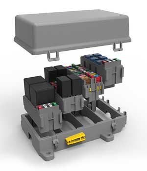
Relays also improve safety by moving the higher current of some components from the switches to the relays themselves. Currently the only relays in the original loom were in the starter solenoid, and a separate one for the horn. I decided to use 4 more, see the table below. The fusebox I used (similar to above) has provision for 4 modules, to be utilised as below:
| Module | |
| 1 | 20 Mini fuses (banks 1 & 2) connected to the ignition (live when on). |
| 2 | 6 Micro relays for Headlights (2), DRL, Horn, Heated Rear Window, and 1 spare. |
| 3 | 2 Standard Relays for indicator & hazard units. |
| 4 | 20 Mini fuses (banks 3 & 4) permanently live (only bank 4 connected to solenoid). |
Bank 3 is not used, so I have provision for 30 fuses! In the end I only intend to use 19, so there will be plently of spare slots, if I add items in the future. My newly designed loom can now be seen by clicking here to see my pdf booklet. You are welcome to use this as a basis for your project, but I accept no liability for any consequences - I am not a trained auto-electrician!
1. Ignition Circuit
This consists of the starter solenoid, the alternator, the ignition switch and the coil/distributor. The solenoid is the hub of the system - it receives the main feeds from the battery and alternator (which is connected to the solenoid, rather than directly to the battery). There is also a secondary feed from the B+ terminal of the alternator - this is the power supply which "energises" the alternator from the battery. This powers the alternator field coils so electricity can be generated as the alternator spins. Another connection operates the alternator warning light on the dashboard. The starter motor is energised by connecting the smaller terminal to the main terminal via the ignition switch. This connection also serves as a feed for the items powered when the ignition is switched on, which is routed through the fuse box for safety.
2. Lighting Circuit
This includes all external lighting as well as the instrument illumination which comes on with the sidelights. I will use three relays, one each for the High Beam, Dip Beam and DRLs. This will route all the wires to the front of the bonnet, as well as behind the dashboard to the instrument illumination and master light switch. Two of the relays will be standard SPST (Single Pole Single Throw) used for the headlamps, and the other relay will be SPDT (Single Pole Double Throw) for the DRL. The thinking behind this is that the DRLs come on with the ignition, and extinguish when the lights are switched on. It was suggested by Gil of Better Car Lighting that these should dim when the other lights are put on, but with my current Honda Civic 'modern' they extinguish, which I prefer.
3. Indicator & Hazard Circuit
This had to be designed from scratch as I was using LED bulbs, so needed electronic flasher 'relays'. However those which fit into the modular fusebox did not have provision for the warning light. I had to use a diode bridge, which I'd never heard of until introduced to the concept by Gil of Better Car Lighting. In the end I didn't use one for my lighting circuit, which was useful as I could use it for the indicator circuit! The circuit I designed was checked by Duncan of Classic Car LEDs who thought it should work!
![]()