This is turning my shell back to a finished car, i.e. lights, bumpers, interior, brakes, fuel system, interior, etc. I often come up with unexpected problems, and have to find solutions in order to go forward! I don't always find time to work on this, hence the gaps between dates!!
To go to the latest post click here.
Friday February 17th 2017
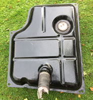
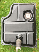
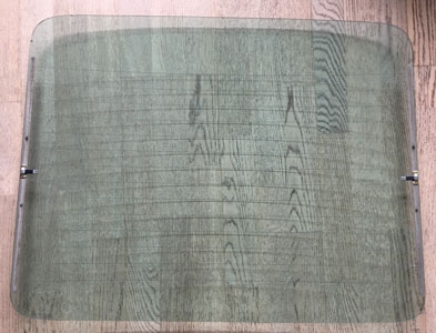
Removed petrol tank & cleaned it up. Cleaned windscreen, wrapped it in bubblewrap & put it on shelf in garage. Put in spare battery, tried to start but not enough. Put original battery on charge.
Saturday February 18th 2017
Cleaned floors of car. Started engine, ran for 10/15 mins. Sounds great! Tried fitting gas struts to bonnet!
Thursday March 16th 2017
Fettle fuel tank to fit. Paint tank and diff & o/d covers in black.
Saturday March 25th 2017
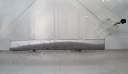
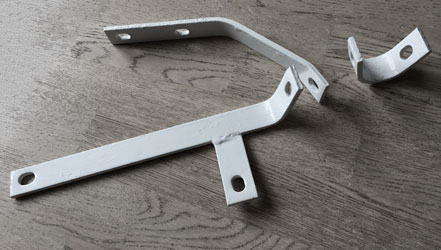
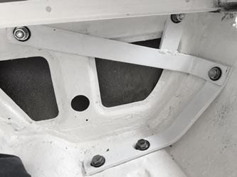
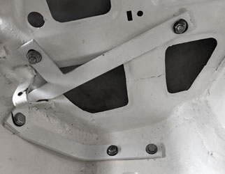
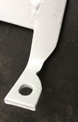
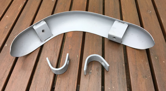
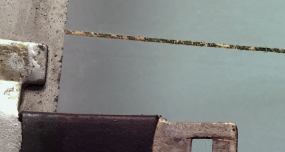
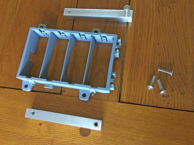
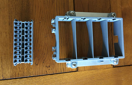
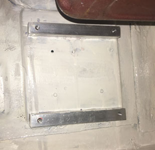
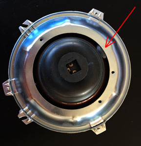
Cut & drill stainless steel angle, fit to rear of boot to strengthen rear exhaust mountings as below left (mounted to bodywork). Clean & paint rear bumper irons, one set below right.
Monday March 27th 2017
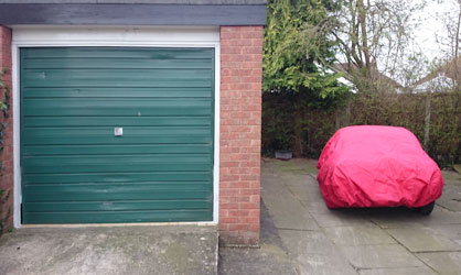
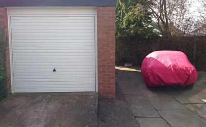
Drove car out of garage for new garage door to be fitted! The old and new doors can be seen below, with the GT6 safely in it's Hamilton cover while the new door was fitted.
Tuesday April 4th 2017
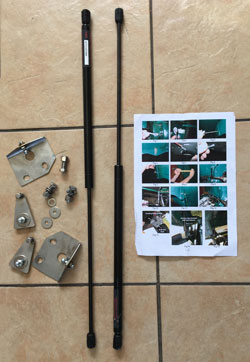
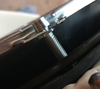
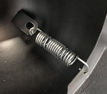
Fitted the TSSC Shop gas strut kit to bonnet. There is a story to this, as I spent a lot of time, and email correspondence with the TSSC trying to successfully fit it. The lower brackets didn't seem designed to fit the GT6 Mk2 at all, and the TSSC failed to send me a single picture of one fitted to a Mk2.
Sunday June 11th 2017
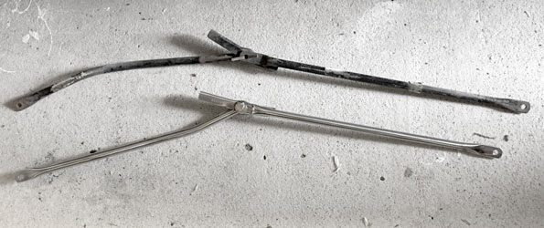
Removed gas struts completely (to send back for a full refund) as found that they were pulling the bonnet back towards the body tub! Ordered s/s conventional strut from Canleys. Started fitting rear bumper 'irons'.
Friday June 23rd 2017
Fitted new stainless steel bonnet strut, see old and new below.
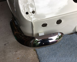
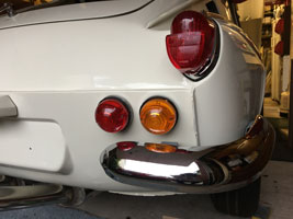
Also fitted LH & RH rear bumper irons with rubber washers and stainless steel fasteners. The LH (see 2nd and 3rd pictures further below) had the be ground away near the bottom to clear the fuel tank bracket, which must have been moved to a new position since the bodywork was done by Southside. The rear LH bumper was cleaned up, painted at the rear and fitted, also with stainless fasteners. The rear bumpers were purchased new in the 1980s, and are still in quite good condition.
Tuesday 4th July 2017
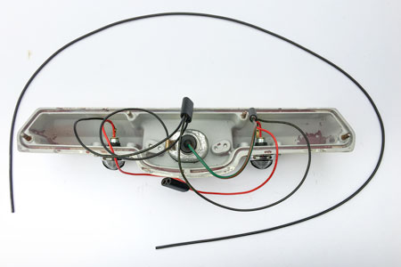
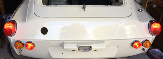
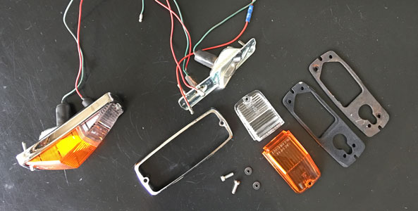
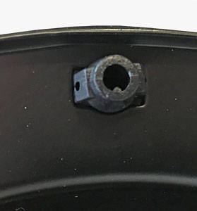
Re-assembled and rewired rear Reversing Light/Number Plate Housing.
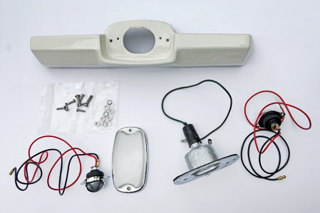
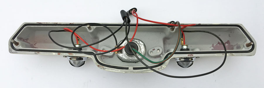
Original parts for these are unobtainable as only the later GT6 Mk2 and Spitfire Mk3 use these housings and Triumph parts suppliers don't list them. I therefore obtained parts as follows:
1. Number Plate Lights : As Triumph Stag Boot Lights...........
2. Reversing Light Lens : NOS Jaguar Series1 E-Type (ebay).
3. Gasket : Made from O Ring Cord Nitrile Rubber.................
4. Fasteners are new stainless steel........................................
5. Everything else was refurbished........................................
Tuesday 4th July 2017
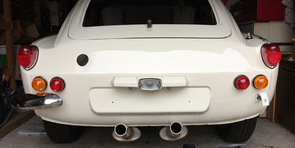
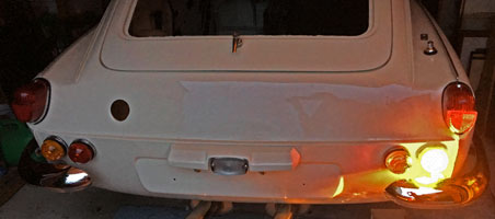
Rear lights fitted. US style additional stop lights are fitted in the holes meant for early GT6 reversing lights (these had to b redrilled as they had been blanked off in the first restoration) as an added safety measure.
Wednesday 26th July 2017
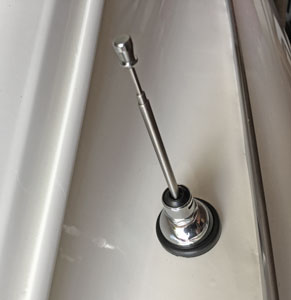
New aerial fitted.
Saturday 26th August 2017
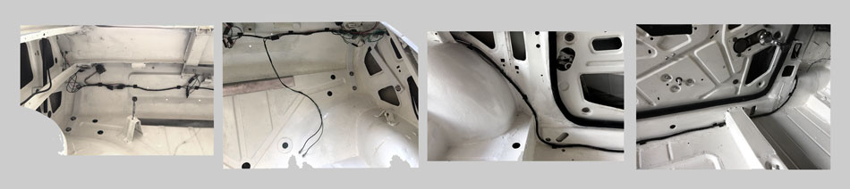
Rear wiring loom now all connected up - first test of rear lights...
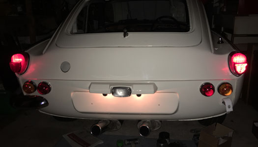
..and brake lights.
Monday 28th August 2017
Rear wiring loom tidied up!
Tuesday 29th August 2017
Painted bumper irons and inside of rear bumper.
Sunday 3rd September 2017
Rear RH bumper fitted.
And rear indicators now working!
Monday 4th September 2017
Diff cover replaced with new fasteners
Wednesday 6th September 2017
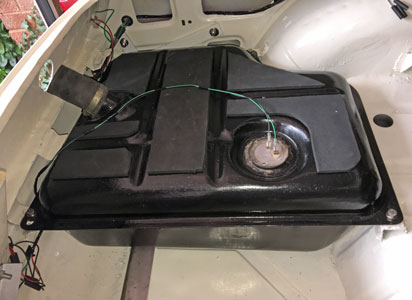
Fitted SilentCoat to fuel tank, then installed it into the car, after a quick rinse with petrol!
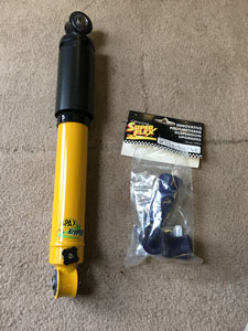
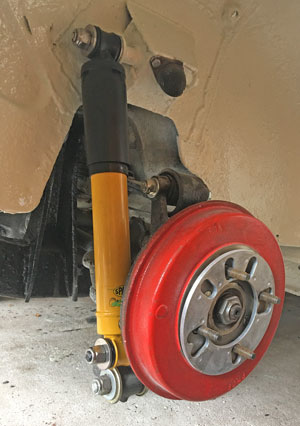
Saturday 9th September 2017
New SPAX shock absorbers arrived yesterday. Bought from JD Motorsport/eBay for a fraction of the price of other vendors, and they were sent directly from Spax Performance Ltd in Bicester so are the real deal!
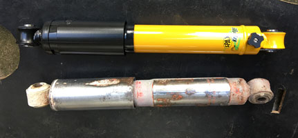
Above are the new Spax and old Armstrong shock absorbers (which I had originally intended to sand down and repaint).
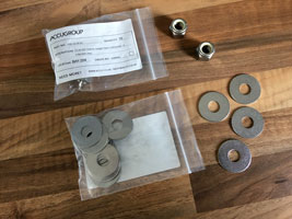
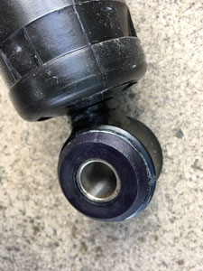
The thick washers which go on either side of the mountings are no longer available. These are 1/2 x 1.3/8" x 3mm (13mm x 35mm x 3mm). I bought some stainless metric ones (see below) which are 12.5mm x 35mm x 1.55mm). The washers are 1.5mm thick, so need to be doubled up to get the 3mm thickness of the original. The centres needed to be drilled out to 13mm to fit.
Sunday 10th September 2017
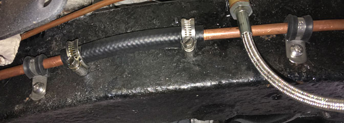
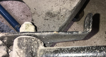
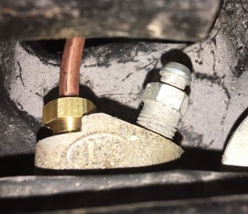
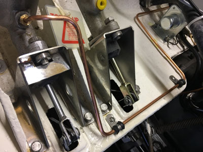
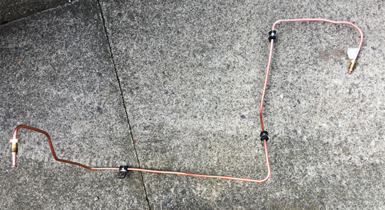
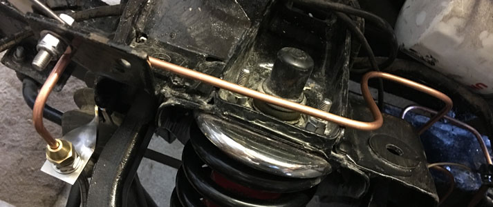
Now for the fuel line from the tank to the engine. The old line was ripped out, and I forgot to photograph it, so I'm not sure how to route the 5/16" copper replacement pipework around the rear transmission! A quick email to Andy Cooke, the TSSC GT6 Register, immediately elicited some images from his MkIII which proved useful. Thanks, Andy!
Monday 11th September 2017
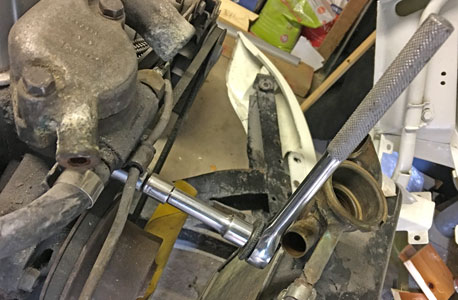
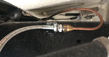
Progess on the fuel line. I was initially concerned with routing it near moving parts, i.e. the rear LH driveshaft. However it appears that this is unavoidable, so I routed it around the smallest part of the driveshaft and just under the transverse leaf spring, keeping it clear of any spring movement, and also away from the handbrake cable.
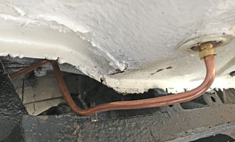
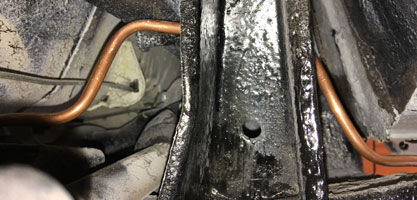
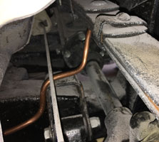
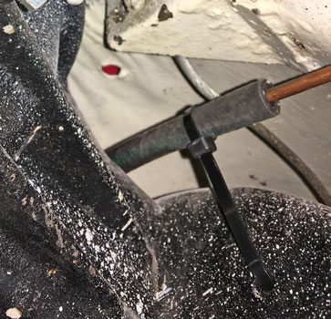
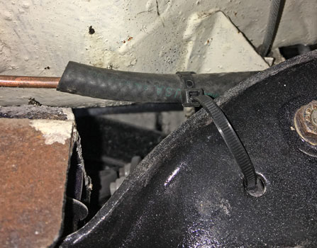
The last picture shows the end, to be joined to the front section by a PTFE stainless steel braided pipe (temporarily fixed by a cable tie). I will leave the fitment of brackets, as a brake line has to occupy the same part of the chassis (see bracket).
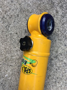
While awaiting the other parts I need, I fixed the poly bushes to the shock absorbers. Hint - don't try to fit the centre tubes first, fit the bushes (using a large metal vice as a press) then the tubes!
Wednesday 13th September 2017
After drilling the washers (see Saturday 9th above) I fitted the LH shock absorber, torqueing the nyloc nuts to 55 lb-ft as per the workshop manual.
Friday 22nd September 2017
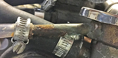
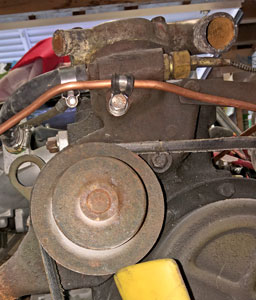
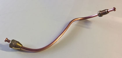
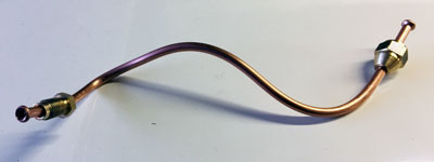
Removed the fuel line from the fuel pump to the carburettor. Hard to get at the nut holding the bracked at the front of the engine, so I had to disconnect the top hoses and move the radiator forward (see below):
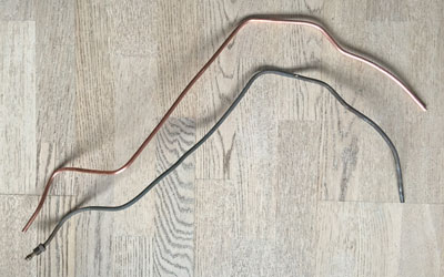
Below is the old fuel pipe with the new one, shaped to match!
And in position:
Saturday 23rd September 2017
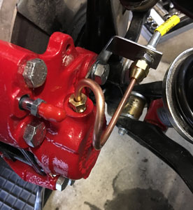
Started installing the brake pipes (while I await the stainless steel braided flexible lines for the fuel pipe), first the pipe on the LHS of the chassis from the engine compartment:

Monday 25th September 2017
With arrival of new stainless bolt and P clip from Grove, refitted 1/4" fuel pipe to front of the engine, and then put back radiator and hoses.
I'm not happy with the corrosion on the overflow pipe coming out of the radiator just under the cap:
It either needs replacing, or just cleaning up? I tried cleaning it up, and it broke off!
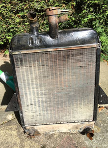
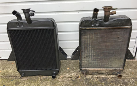
Tuesday 26th September 2017
Looking at the radiator again, I decided to invest in a new one. Which to go for, they range from around £200 to £250 from eBay or the usual Triumph suppliers for brass, and £188 to over £500 for aluminium. I couldn't justify aluminium, so in the end plumped for this one from Triumph-Recycler:
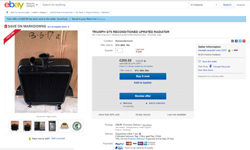
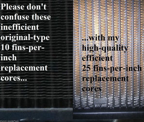
Why this one? Well it looked nice in the pictures. Seriously, the specification sounded good: "This is a genuine radiator professionally reconditioned with a new, modern, uprated 25-fins-per-inch core to give better cooling than standard or aftermarket radiators. Pressure-tested leak-free to 35psi & won't fall apart like those poor-quality Asian imports!". I did a deal with Simon Holland with my old radiator in part-exchange. He claims he is an enthusiast (having been a continuous Triumph owner/driver and member of the TSSC since 1988) AND trader who makes a very modest return for his investment in the marque, the vast majority of that coming from the sale of new parts, many of which he has manufactured locally with a significant personal investment for tooling and production. He is also a member of the National Association of Radiator Repairers and a Federation of British Historic Vehicle Clubs Trade Supporter. Images of the radiator appear below:
An efficient radiator should obviate the need for an aftermarket electric fan (although many are questioning the efficiency of these, often reverting to mechanical fans).
Thursday 28th September 2017
Fitted the badges to the rear.
Removed the radiator. Lots of very brown water came out of the bottom (was clear at the top!)
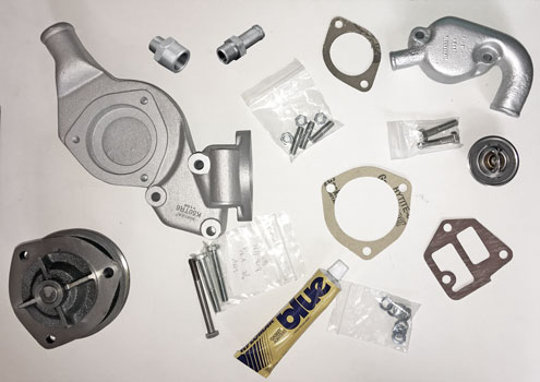
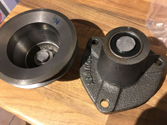
Ordered new water pump and Inpeller housing from Chris Witor.
Friday 29th September 2017
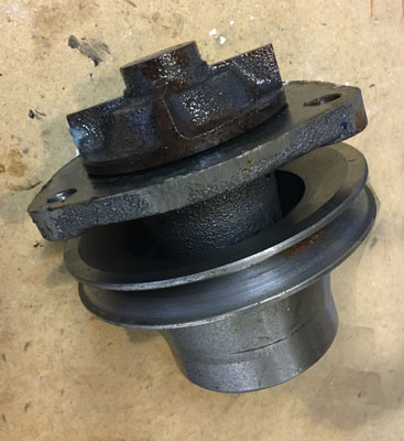
Removed the water pump housing.
Saturday 30th September 2017
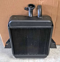
'New' radiator arrived from Triumph-Recycler:
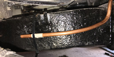
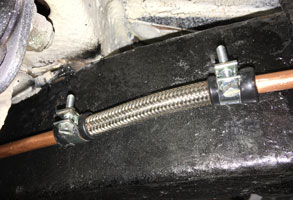
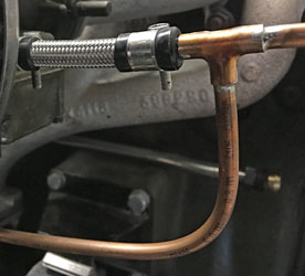
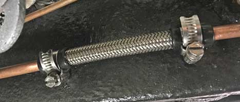
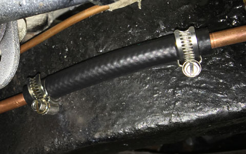
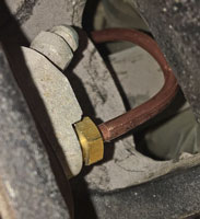
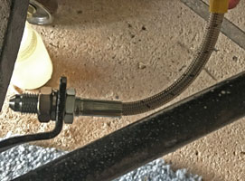
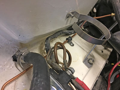
I fitted the flexible rear PTFE stainless steel braided fuel pipe joining the rear fuel pipe to the one running along the LHS chassis member to the engine. I had great difficulty cutting this tubing, trying an angle grinder and duct tape first but it still frayed the braiding too much to get the rubber end cap on. Eventually I used a combination of masking tape (it doesn't stretch as much as duct tape) and a junior hacksaw. I think the result looks quite neat:
Wednesday 3rd October 2017
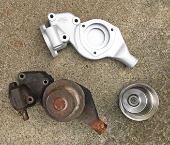
New light alloy impellor housing and water pump arrived from Chris Witor, with old below.
Monday 9rd October 2017
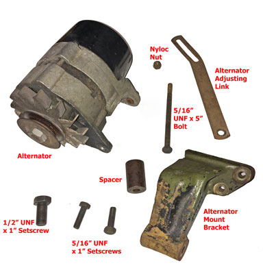
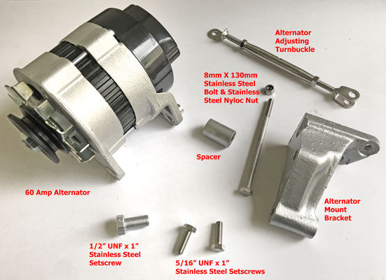
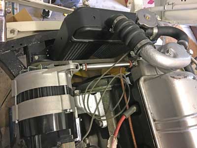
Alternator assembly ready for refurbishment.
The alternator mounting bracket is very heavy and I was tempted by the alloy replacements available. However they look somewhat different (see below)
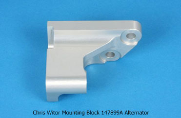
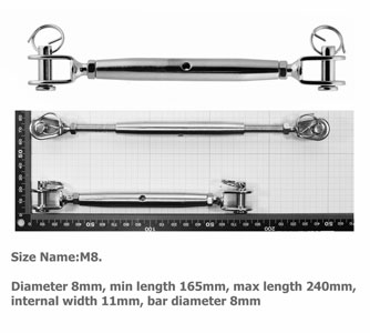
The reason, according to Chris Witor "The GT6 alternator was dropped to clear the bonnet", so fitting his bracket to permit the fitting of the 1088mm 2.5PI fan belt may well make the alternator foul the bonnet, a risk I was not prepared to take! The fan belt used in my car from the engine change in 1980 was a Chrysler 7100743 (Hillman Imp) and is 1175mm long x 9.5mm. The standard GT6 fan belt would not fit as the 2.5 engine has a larger crankshaft pulley. This fan belt was a tight fit, it would not come off without the aid of a long screwdriver to lever it off the pulleys with the existing GT6 adjusting link, so in a new setup a longer belt would be preferable! I am tempted by the use of a turnbuckle as proposed by 'Ben' in his GT6 / Spitfire DIY alternator bracket improvement (to visit the appropriate page on his his quick fix website click here). I have ordered one from Amazon, of all people, for only £5.05! This has a 'range' of 165mm to 240mm which compares to the 150mm to 205mm of the original. Hopefully I can try a 1200mm belt, but I'll wait until it's all reassembled and I'll measure it before ordering one.
I'll have to modify it, as per 'Ben' below
Thursday 12th October 2017
Water pump components ready to go back on the car, with stainless steel fasteners and other parts.
Friday 13th October 2017
New alternator assembly parts, ready to go back onto the car.
Wednesday 18th October 2017
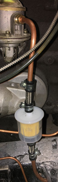
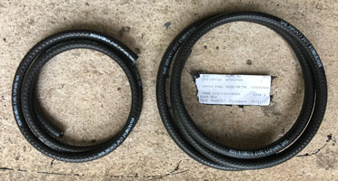
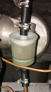
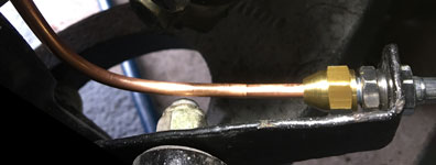
Completed renewing more fuel lines. This time the 5/16" id section from the entry of the long pipe from the tank as it exits the chassis at the front, to the fuel pump. Please note a fuel filter is now fitted, to stop any debris from the tank getting through!
Friday 20th October 2017
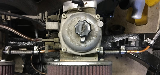
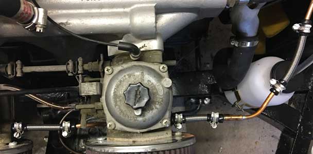
New 1/4" id fuel lines by the carburettors:
Sunday 22nd October 2017
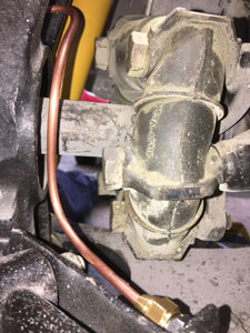
Fitted new water pump to water pump housing.
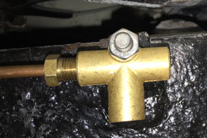
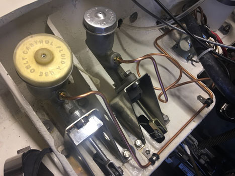
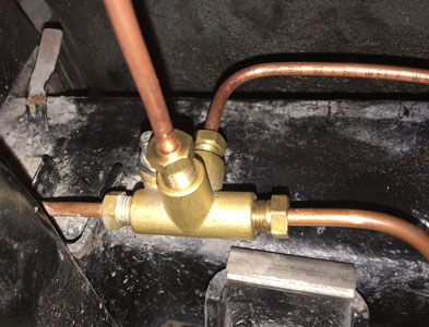
Also fitted 3-way brake union at the LH rear of the chassis, and connected the pipe from the front.
Tuesday 24th October 2017
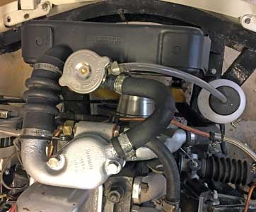
Did quite a lot today, as the parts arrived from Chris Witor. I fitted the water pump housing and alternator, ordered a 1200mm fanbelt from Bearing King. As can be seen below, the old 1175mm fan belt won't quite go on! The capilliary sender for the water temperature gauge almost fouls the thermostat housing. I contacted Speedy Cables to see if they could convert my combined water temperature/oil pressure gauge to electric, but they declined.
Thursday 26th October 2017
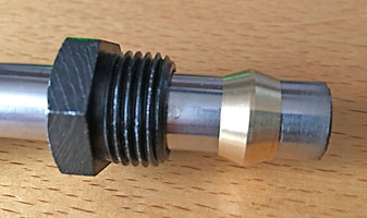
Problems fitting the stainless steel pipe from the heater to the water pump. The original olive had split, so I bought a new olive and sleeve nut from Paddocks. When I came to fit them, the olive and nut wouldn't fit over the pipe (although that came from Paddocks a couple of years ago). A quick email to them elicited the response "You are more than welcome to bring them in I'm not sure there will be anything different but we can have a look" which didn't inspire confidence! However I went there and they said the pipe was faulty, would be sent back to their supplier, and replaced it with a new one FOC, what great service! It all fits perfectly now (see below).
Friday 27th October 2017
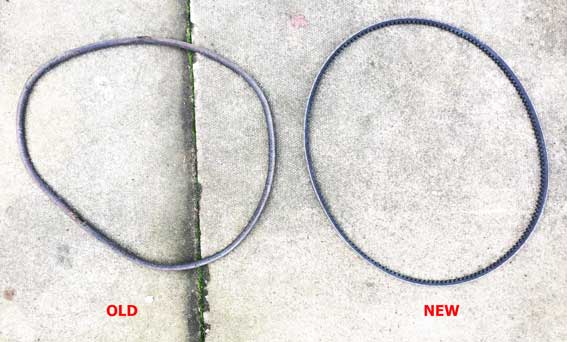
New fan belt arrived from Bearing King. Much too long, I shouldn't have assumed old one was 1175mm. On measuring it turned out to be 1130mm! I have now ordered another one 1150mm long. When I get the right one, I'll get a spare!
Above the old (1130mm) and 'new' (1200mm). I've managed to refit the originally fitted (Hillman Imp) fanbelt.
Saturday 28th October 2017
Fitted new stainless steel pipe from the heater to the water pump. Then fitted the 'new' radiator and associated hoses. Filled with the antifreeze solution previously drained, then put around half a gallon of fuel into the tank. Disaster, leaks everywhere! The clips aren't tight enough. Tried one of the small Hi-Grip hose clips I got from Grove Components to try, and this seemed to tighten much better, so ordered more, which will hopefully come on Tuesday or Wednesday. I also tried to start the engine, but didn't start although good oil pressure achieved. Then found the lead from the distributor was not connected to anything!
Monday 31st October 2017
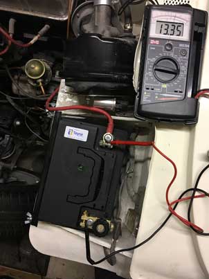
New Hi-Grip clips arrived from Groves. Fitted them, put a little petrol into the fuel tank, tried to start. The solenoid clicked, but nothing else, so put the battery on charge again! I suspect the battery has had it, as it has spent long periods without being charged up.
Above, the rear join, on the LHS chassis. Below by the carburettors.
Thursday 2nd November 2017
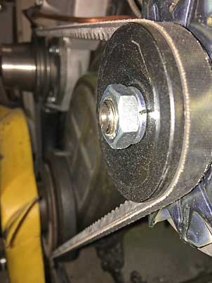
New fan belt arrived. This time it's the right length!
Also I bought a new High Torque Starter Motor from James Paddock. It is British made, by WOSP in Aylesbury. It wasn't on Paddock's website (they only listed one for the Herald) but when I called, they had a GT6 specific model in stock.
Friday 3rd November 2017
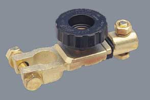
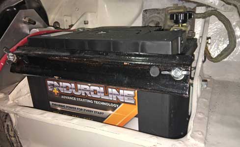
To get the car started I ordered a new battery, and also cleaned all the earth leads, as I believed that these would be the most likely culprits. I also decided to upgrade the starter to a High-Torque version. I got the battery from Tanya Ltd in Abergele. Ordered yesterday afternoon, delivered this morning! I also decided to stick with their Enduroline 075. I could have upgraded to a larger battery, I believe the 072 would have just fit, and the terminals would have been at the front. However with a more powerful alternator and more efficient starter I didn't think this was necessary. Also a bigger battery wouldn't have left room for the Dis-car-nect Immobiliser and Battery Cut-Off Switch, which I like, as it cuts off power to the car circuits when the car is unattended.
After all that it still clicks when I try to start the engine, but the new battery is not yet fully charged. Tomorrow, I'll try again. If it still doesn't start, I'll check the battery voltage (should be over 12.6 volts, apparently).
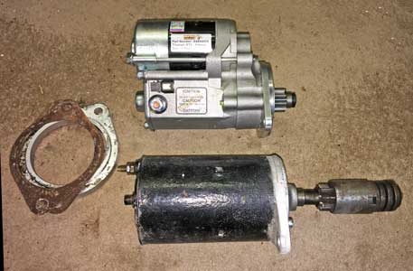
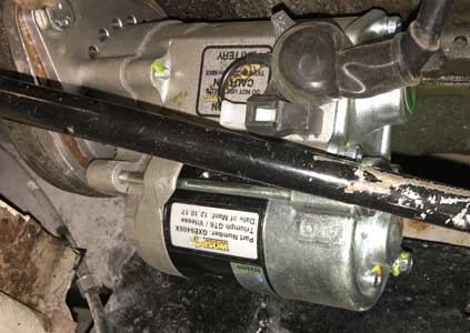
Above the old and new starter motors. Below the new starter motor up close, and in position. As it was an inertia starter being replaced, the black link wire is attached to the battery stud post (bottom left).

Saturday 4th November 2017
The battery is now fully charged, voltage now 13.35 volts (well above 12.6 as specified above). The car started almost first time, in spite of the fuel pump having to get petrol to the carbs (the high-torque starter being very effective). This is the first time the engine has run since 27th March. The fuel lines didn't leak either! Runs well with good oil pressure.
Monday 6th November 2017
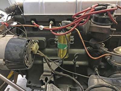
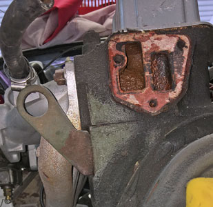
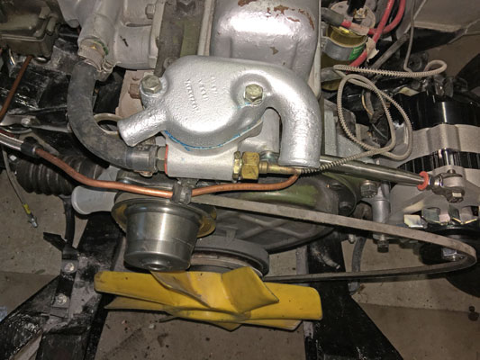
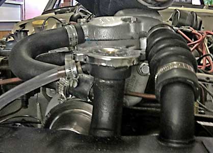
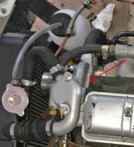
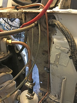
Dealt with a petrol leak from the left carburettor, caused by a sticking float. Tried to get the bottom off the carb, but it would't come off after removing the 5 screws. However, in the hope of the movement of this that the float would unstick, I reassembled and fortunately when I ran the engine again the leak had stopped. On running the engine up to temperature, a small leak from the top of the water pump housing manifested itself with a hiss of steam and bubbling. Tried tightening the top bolt, but this had no effect. It's difficult to get this really tight as the fuel pipe bracket is also attached by this bolt. I may have to remove the housing and re-attach it with a new, perhaps thicker gasket. Below a picture of my engine from above showing the location of the leak.
Thursday 9th November 2017
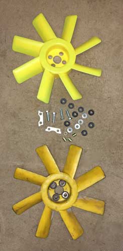
Various items arrived today:-
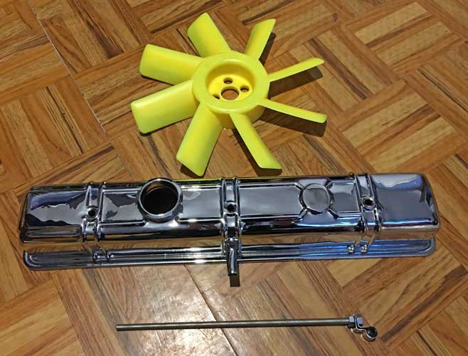
From top to bottom: New OE 8-bladed fan (the original has 'wobbled' after getting a wire caught around it a while ago); My spare 2.5PI rocker cover after re-chroming by S&T Electro-Plate in Bristol; A 5/16" UNF Threaded rod and a stainless steel fuel pipe bracket from Chris Witor with a polyurethane bush. Off to the NEC tomorrow!
Saturday 11th November 2017
About to work on the car when my dear wife Liz suffered a sudden and totally unexpected TIA (Transient Ischaemic Attack or mini-stroke).
Tuesday 14th November 2017
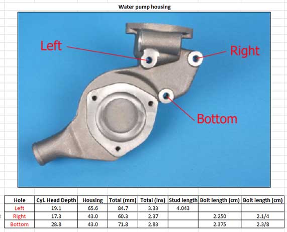
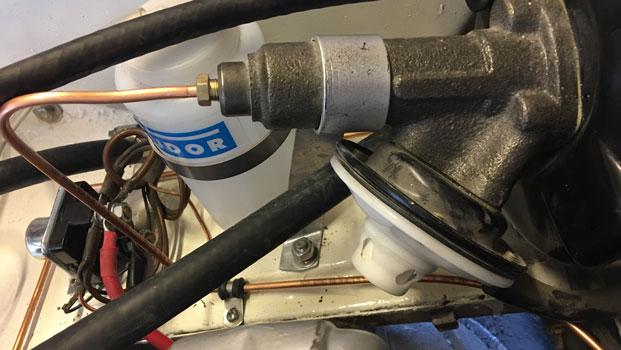
Liz much better, gone out with Becky - so while they were out I removed the radiator and the water pump housing and ordered a fan fitting kit from ANG Classic Car Parts. My plan is to replace the wp housing with a thicker, or multiple gaskets. I got a couple from James Paddocks and they seem much thicker than the one I got from Leacys which was paper thin (see remains below). Also I intend to replace the bolt which carries the fuel line bracket with a stud, as tightening this bolt sufficiently (20 lb. ft.) with the bracket in position was difficult. With a stud, it will be easier to tighten, as the fuel line bracket can be attached afterwards with an additional nut (also see below). Hopefully this will cure the leak!
Sunday 19th November 2017
There's a problem with the rear fuel pipe (LHS of rear chassis, below) - it keeps leaking. I've tightened it twice, blaming the cold weather. However I've decided it's no longer safe, so I have reluctantly ordered some 'Ethanol Proof Fuel Hoses by Gates' from Moss. It won't look as good, but should be leak free! To find out more about these hoses click here.
Tuesday 28th November 2017
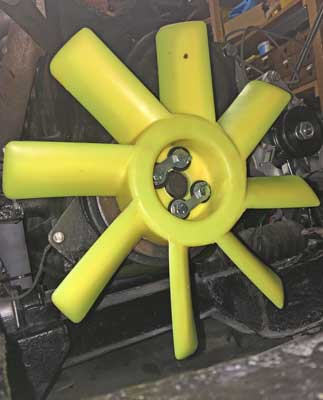
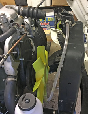
Liz is getting much better, so spent an hour or two in the garage today. Fitted the new fan. The rubbers in the fitting kit I got from ANG did not fit easily, and had to be forced into position with a nut, bolt and washers.
I then ran a tap down the cylinder head holes for mounting the water pump housing and then cleaned the mating surfaces, before measuring the holes and the housing to see if the bolts I had used were not too long. Also I needed to calculate the length of the stud required for the mounting with the fuel line bracket. More about this next time...
Monday December 18th 2017
The results of my calculations for the fixings for the water pump housing appear below:
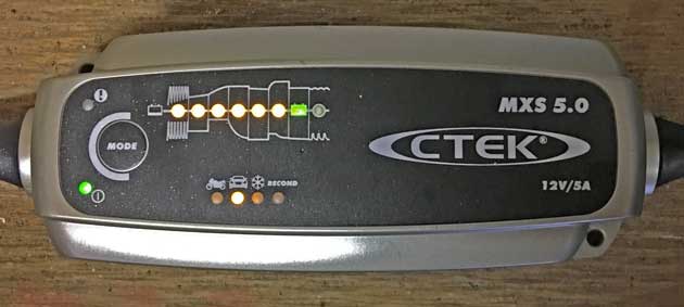
Finally got around to refitting the water pump housing, radiator, hoses, thermostat housing etc. I also finished the extension socket near the front n/s of the car so I can have the CTEK battery charger permanently connected without an extension cable.
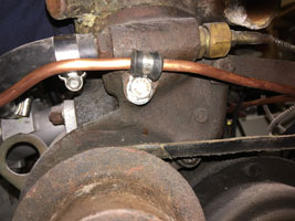
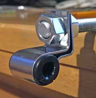
Above is the stut, substituted for the bolt, with the new stainless steel/polyurethane fuel pipe clip from Chris Witor fastenened with an additional nut. The reason for this arrangement is that I can torque up the nut holding the water pump housing to 20 ft lbs, without having to do the same to the fuel pipe clip, which then turns!
Friday 22nd December 2017
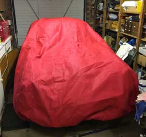
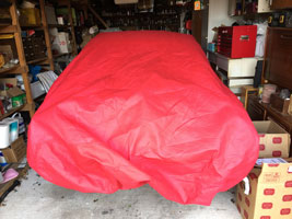
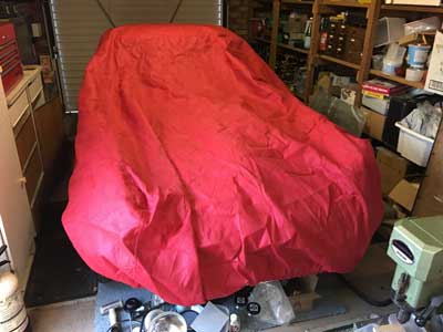
Finished by closing drain valve on radiator, checking all clamps are tight, and refilling with antifreeze. Now the car is all covered up in red for Christmas, and connected to the charger!
Thursday 1st March 2018
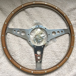
Still too cold to work in the garage (-1 at the moment) but I took advantage of Rimmer's sale by treating myself to a couple of items: a new wiper motor and a Moto-Lita steering wheel!
Monday 5th March 2018
Now warmed up to 8 degrees, so uncovered car and tried to start it. However failed, and found that the fuel system was bone dry - all the petrol must have leaked from the rear join (see 19th November). I then went to replace the fuel hoses with the Gates Barricade, ethanol proof ones. However I found I had ordered the wrong sizes, 3/16" and 1/4" instead of 1/4" and 5/16" back last November, so I've ordered some more from Moss Europe.
Saturday 10th March 2018
Fitted the new Gates ethanol proof petrol pipes to rear and either side of the fuel filter below the fuel pump.
Tuesday 13th March 2018
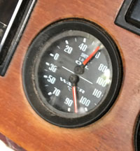
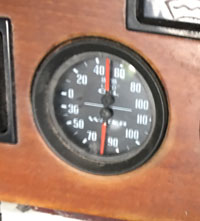
Filled the fuel tank with the best Esso Synergy Unleaded Petrol, and tried to start the engine. No fuel leaks this time! Started, but couldn't maintain revs so I suspected that the carburettor pistons were sticking. I then freed up the carb pistons by pressing the lifting pin underneath a few times. It now started properly, so I ran the engine for a few minutes - it's the first time I've had the engine running since 4th November last year! Oil pressure was good (60psi see below), but I had two concerns: (1) the engine was vibrating at the front (this could be clearly heard). Either the new water pump is vibrating or the new fan is! (2) the water temperature went up to 95 degrees and rising, much hotter than the usual 80 degrees. Later, when I took off the radiator cap the water level seemed low (probable air locks), so at a future date I'll top up the system and try again.
Wednesday 14th March 2018
Bought some more Halfords Silicate Anti-Freeze and Coolant (ready mixed) and topped up the radiator - it took at least another litre, presumably there were air locks.
Thursday 15th March 2018
Started up car again and ran for 20 minutes. This time the temperature stabilised at 80 degrees (see below). I also emailed Chris Witor about the water pump as a slo-mo video taken on my mobile phone clearly shows a wobble (I bought it new from them last year).
Friday 16th March 2018
Had a response from Chris Witor: "Try running the engine briefly with the belt removed to see if the vibration goes away". I did this, this afternoon, and there was no vibration at all, so I told Chris via email and am awaiting his response. P.S. Just had a reply: "Best return that one for replacement. We will Cover £7.50 of the return shipping cost. If you need one in a hurry, best pace a new order, we can refund when we receive the faulty unit". I duly ordered another one which I'll fit at the same time as removing the faulty one.
Friday 23rd March 2018
New water pump duly arrived from Chris Witor, with the pulley sheared off the pump (see below)! Poorly packed, I've emailed Chris asking for a full refund. I'll either buy another from James Paddock (collection), get the old one refurbished, or get an alloy one. Comments from Chris "Sorry to see the pump was broken in transit. I have sent out maybe 200 pumps and that's the first to get damaged in transit. Most are wrapped less well than this just being within a bubble wrap bag within an express pack bag. It must have been dropped from a height or thrown around in transit. I will put in a claim. By all means get one form another supplier, but you may find it is of the same origin. Failure of these pumps has been around 1% which is pretty good. In the past we supplied Unipart pumps which all leaked within 500 miles... " The make was County Motor Factors, and it was marked "Made in India". I emailed Paddocks and they say theirs is the same make, so I'll probably get one from them, at least I can collect it!
Sunday 25th March 2018
Removed the wobbly water pump, I'll send both back to Chris Witor tomorrow for a refund. In the wobbly one, the bearing has quite a bit of play, no wonder it wobbled!
Tuesday 27th March 2018
Fitted two stainless P brackets to secure rear fuel pipe to the chassis.
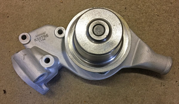
Thursday 29th March 2018
Finally fitted the new water pump, hopefully this time without the 'wobble' (it's the same make). I got this from James Paddock yesterday, only £36. It is made by County Motor Vehicle Components (see detail from the box it came in below). Ignore the "England", it is made in India. According to Chris Witor, failure of these pumps has been around 1% which is pretty good". I was considering having the old water pump reconditioned, Tim Goldthorp of Classic Quality Parts Ltd would have done it for £80. He specialises in Jaguar components but with the GT6 the pump would be stripped down, shot blasted, new bearings and seals fitted and rebuilt. They use ceramic warfare seals which last far longer than any original seal and make the pump work more efficiently. Unfortunately I couldn't find the old water pump, so opted for the new replacement. Typically I found it later! I ran the engine for around 10/15 minutes and this time no untoward vibration from the water pump.

I also made and fitted the short brake pipe from the rear n/s wheel cylinder to the bracket holding the flexible pipe. Not easy, my first effort had to be thrown away! Also, the one supplied in the Automec kit was far too long, so I did the right thing buying the brake pipe flaring tool!
Friday 30th March 2018
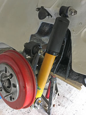
Fitted o/s rear shock absorber, rear o/s flexible brake pipe and connected the brake pipe running under the car from the n/s brakes to this o/s flexible, see below.
1. Cleaning the thread of the upper shock absorber link with die (to remove paint).
2. New shock absorber (Spax adjustable) in position with new stainless nuts and washers.
3. Brake pipe connections (o/s).
Next job, the brake pipe from the rear o/s brake cylinder to the flexible (see above right picture).
Sunday/Monday 1st/2nd April 2018
Not a successful day! Tried to make, shape and fit the rear o/s brake pipe from the flexible (above) to the wheel cylinder. First, the bracket mounted on the hub was bent, so this had to be straightened (see before & after below). Then, two attempts to make the pipe failed - this is not easy at all with no original to copy or photograph in the workshop manual. In the middle of the third (and hopefully last) attempt I had to take the dog for her afternoon walk and afterwards failing light and cold conditions (6 degrees) discouraged me from continueing.
Continued on the next day by completing the brake pipe, in spite of foul weather.
Care was needed to clear the driveshaft and the rotoflex coupling (see above)!
Friday 20th April 2018
It was a lovely day, and Neville & Pat had returned from their stay with us, so I took the car out of the garage for the first time since March 2017! I drove it up and down my drive, checking that all gears worked i.e. 1st, 2nd, 3rd and 4th (as well as reverse!), which they did. I took advantage of the empty garage to give the floor a good clean.
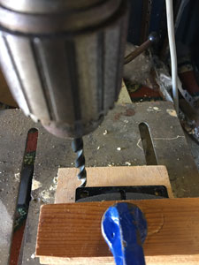
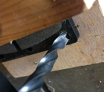
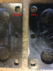
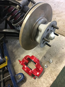
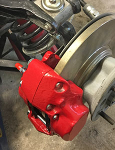
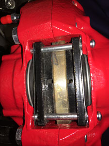
Next, I started to prepare for my next job, the fitting of the front disk brake calipers (rebuilt by BiggRed). As I was fitting the special MINTEX disk pads to a car using Type16P Imperial calipers, the pad pin holes needed to be drilled out to 1/4" diameter to suit the larger pad pins. I did this on the pillar drill (which is more accessible when the car is out of the garage), although I found that 0.25" was insufficient so did it with a 7mm drill (0.275"), see below.
Monday 23rd April 2018
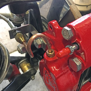
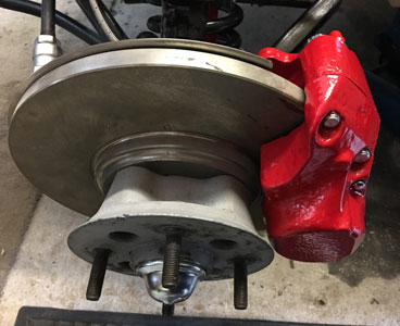
Jacked up the car and removed the front o/s wheel to fit the front brake caliper, together with the brake lines (flexible and copper). On rotation the disk caught slightly on the caliper, so I adjusted the tapered hub bearings as they were a bit slack, and now it spins without catching. Had trouble making a suitable brake pipe to go from the bracket attached with the top caliper bolt, so left this for another day! Fitted the Mintex pads with the anti-squeal shims.
Thursday 26rd April 2018
Finally made and fitted the brake pipe from the bracket to the o/s front caliper, see below. Regreased the bearing and fitted a new split pin and grease cap, refitted the wheel and lowered the car to the ground. Next job, the n/s.
Saturday 28th April 2018
Done the same as above on the n/s. Managed to get the brake pipe right first time, practise makes perfect!
Tuesday 1st May 2018
Fabricated and fitted the brake pipe from the master cylinder to the brake servo. I had to disconnect the clutch pipe, but hadn't been happy with it in any case, it was too long!
Friday 4th May 2018
Finally finished fabricating and fitting the new clutch pipe from the master cylinder to the slave cylinder on the third attempt!
Saturday 5th May 2018
Finished the last two brake pipes, not a walk in the park at all!
The pipe (above left) goes from the 4-way union on the n/s chassis member (above right) to the brake servo. This pipe was discarded as it went wrong (see kinked pipe top right as I bent it in the wrong direction!). This copper pipe bends very easily but does not like being bent back or in the opposite direction as it hardens (case hardening?). Therefore, when I made a mistake in the direction of a bend (easy to do off the car with a bending tool), I had to thow it away and start again. I eventually got it right (see below). I try to route the pipes neatly and don't follow the most direct route, clipping where possible with stainless steel P clips.
Below is the pipe from the front n/s bracket near the brake caliper, to th 4-way union, with which I succeeded first time!
Monday 7th May 2018
I was worried about the brake pipe running over the rear axle, as it was quite long (around 3 ft) and only secured at each end. I have heard that unsecured copper pipes can suffer fatigue fractures if they vibrate unduly. In the end I slipped a short length (around 1 ft) of rubber fuel pipe over the brake pipe wher it goes over the rear differential and secured each end of this to each side of the rear differential carrier with plastic ties (using a convenient hole), see below. Next, bleeding the clutch and brakes.
Thursday 17th May 2018
A while since my last time on the car, as we spent a few very enjoyable days in Prague! Re bled the clutch, using my Gunson Eezibleed Kit. Then I tried to start doing the brakes, but found that the kit contained no caps large enough to fit on the brake master cylinder. I decided to buy a new cap (from trusty James Paddocks) and flatten the old one and drill a 9.5mm hole so the Eezibleed pipe will fit (see below in action).
Sunday 20th May 2018
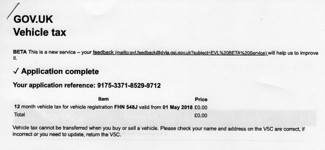
Just because I can, I "taxed" the car today, as from today cars over 40 year's old no longer need an MoT (it is already insured). When it is finally roadworthy and I take it out onto the road, I will get it MoT'd (or an equivalent mechanical check).
Monday 21st May 2018
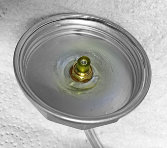
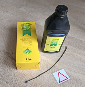
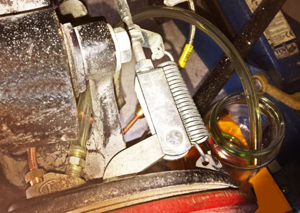
A bad day! I carefully bled the brakes, starting with the furthest from the master cylinder and ending with the nearest. I then tried the brake pedal. It just went down to the floor, so I pumped it a few times to no avail. I then got out of the car and I then noticed a large pool of brake fluid under the car! On further checking I found that the union joining the two front to rear brake lines in the middle of the car was the culprit. One end was tight, but the other was only finger tight, hence the £30 worth of fluid on the floor. I tightened this, and will try again, when I've bought another litre of DOT5 fluid from James Paddocks.
Thursday 24th May 2018
Finally bled the brakes, having purchased more fluid yesterday, with no losses! Next job is to get the car out of the garage and test them. I suspect another bleed may be necessary, as the pedal tightens up after one pump, but this may be the servo.
Saturday 26th May 2018
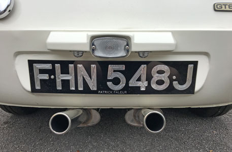
Drove the car out of the garage today! To confirm the car's identity (now it's "taxed") I fitted the rear number plate. The brakes work, but an extra pump on the pedal inproves them! I'll have to try the recommendation in the Lockheed servo installation instructions to "crack open" the brake pipe tube nut at the servo outlet connection whilst depressing the brake pedal.
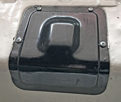
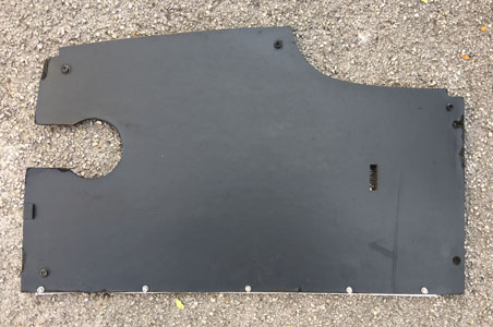
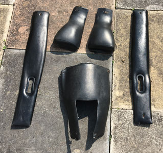
I did some work on the inside rear of the car, installing the (original) spare tyre and the fuel tank board. The spare needs the tyre removing, the wheel refurbishing, and a new tyre fitting. The spare wheel board needs some minor fettling to get it to fit properly (it's not the original) and painting black to match the original left hand board.
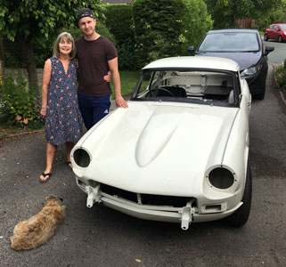
Below right is the car with my wife Liz, my son Jason and Cleo our Border Terrior who has a talent for appearing in photos! It's strange to think that I wasn't much older than my son when I bought the car (he's 29, I was 31).
Monday 28th May 2018
Drove the car out of the garage and "cracked open" the brake pipe (see Saturday's blog). Brakes are reasonably effective at low speeds, but still require a second pump for the pedal to become hard. I'll have to bleed them again at the wheels. Then I turned my attention to the rear boards. I repainted the fuel tank board (matt black) and re-attached the metal strip at the right hand edge (to locate the left hand edge of the spare wheel board) with stainless fasteners. I also got some of the interior trim from the cupboard in the garage, and cleaned it up!
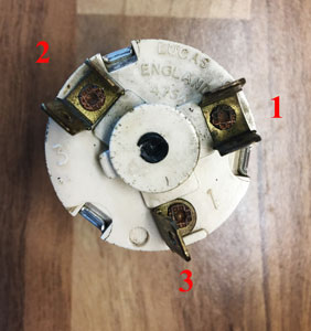
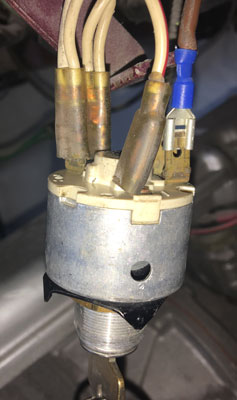
Tuesday 29th May 2018
Started thinking about the front wiring loom which I intend to remake from scratch! Started by removing the ignition starter switch (Lucas 47SA). I was a bit puzzled, as the wiring diagram didn't match the numbers on the switch. I attached a meter, and the 2 double terminals 1 and 2 are connected when the ignition is switched on, and the single terminal 3 becomes live when the key is turned further against a spring. Looking at the second picture the brown wire is the live feed (from the battery via the solenoid) and the 4 white wires go to the various components. When the ignition is switched on the live feed is connected to the white wires. When it is turned further the white/red wire which goes to the solenoid becomes live and the starter is activated. However if the first picture is examined terminal 1 has a "2" near it, terminal 2 has a "3" near it and terminal 3 has a "1" near it!!!
The principal of the GT6 wiring is that all circuits controlled by the ignition come from those 4 white wires. They are allocated as follows:
1. Ignition warning light & alternator.
2. Ignition coil & distributor.
3. Oil pressure warning light & switch.
4. Circuits protected by the top fuse (heated rear window; indicators; heater;
fuel/temperature gauges; brake lights; wipers; reversing light).
The middle and lower fuses control the parking & number plate lamps, the horn, the hazard lights, the headlamp flasher and the interior light and are permanently live (i.e. can be used without the ignition being turned on).
The aim, therefore is to replace the 3 fuses with possibly 12, one for each circuit using a new fuse box mounted in the passenger compartment. Currently the only relay is for the horn. I intend to add relays for the head lamps, and possibly the heated rear window which draws a lot of current. As the overdrive is J-Type, it doesn't need a relay as the current drawn is low.
Wednesday 30th May 2018
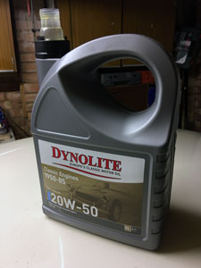
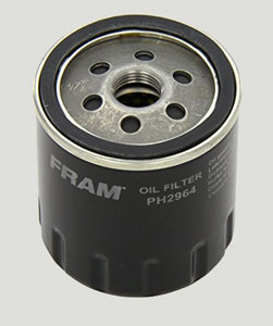
Did an oil and filter change, as this hasn't been done since 2013. Used a 'quality' oil (Dynolite 20/50 from Paddocks) and the Fram PH2964 filter supplied to fit the Spin-Off Oil Filter Conversion Kit . As I aways do, I removed the spark plugs and spun the engine with the starter until the oil pressure gauge showed pressure. I prefer to do this, as I don't think it's a good idea to run the engine under load, until the new oil is circulating.
Saturday 2nd June 2018
I cleaned up the Lucas front indicator/sidelight assemblies, and fitted them. They are supposed to be attached with FZ34044 nut retainers, but I prefer to use stainless steel nuts and washers. Which fiitted the threads of the captive studs? M5!
Monday June 4th 2018
Did most of todays work working on designing the new front wiring loom. Decided how to allocate the fuses in the new modular fuse box. For more information, visit the "Wiring Loom" section of My GT6/Latest Restoration 2 or click here.
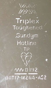
Also cleaned up the rear window, and tested the heating elements with a test multimeter. Initial dismay, finding that most of the 14 wires are not conducting i.e. apparantly broken, turned to mild euphoria when I discovered that scraping the corrosion (see below) from the wires showed they were conducting. This screen was brand new in 1981 (it was a Triplex Toughened Sundym Hotline for a Mk3, hence the wires are across instead of up and down, as the original Mk2). Hopefully, when connecting the connecting strips on each side to the car's wiring loom, the heat generated will make the corrosion flake off (I daren't sand it off which will scratch the glass).
Thursday June 14th 2018
Finally worked out a circuit diagram for the headlamps, Sidelights and DRLs (Daytime Running Lights) I will fit in place of the pilot lights in the headlamps, all using relays in a new fusebox!
.jpg)
Saturday June 16th 2018
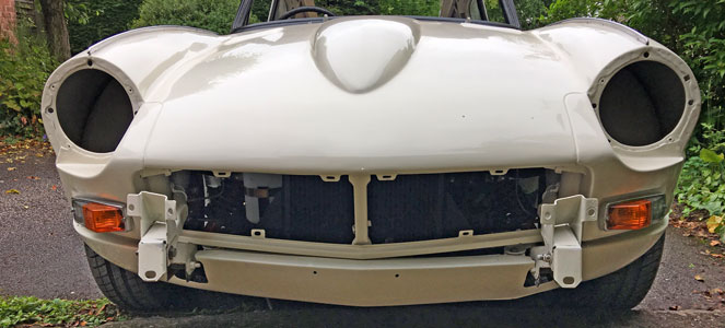
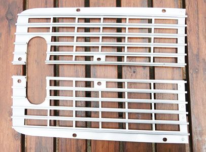
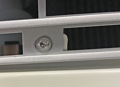
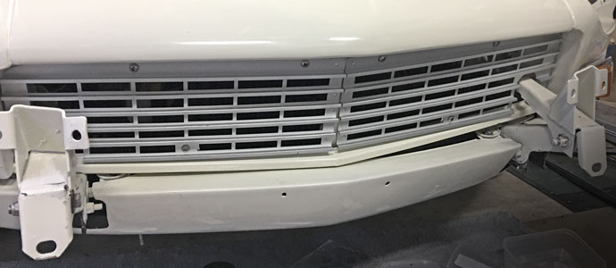
Sprayed and fitted front aluminium grills (as fitted to early Mk2 GT6s). The grills were given to me some time in the early 1980s at a TSSC local meeting. As they are now sought after, I had them soda blasted, and then gave them a few coats of silver car enamel and then clear lacquer. Fitted with M6 stainless button bolts which I think look very good!
Thursday 21st June 2018
Assembled the headlamp parts, trying to work out how they went together!
Thursday 27th June 2018
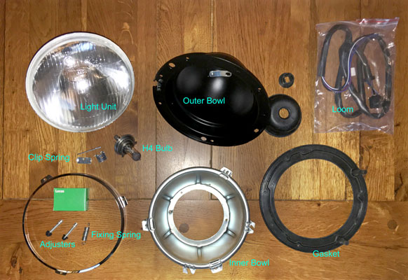
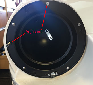
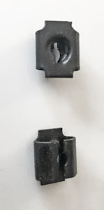
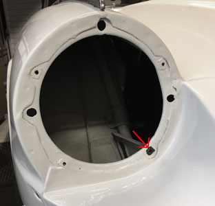
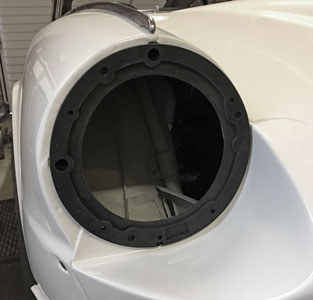
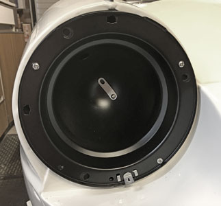
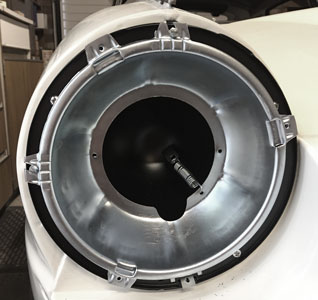
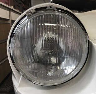
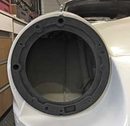
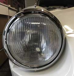
Very hot (over 30 degrees yesterday afternoon)! I've worked out how the headlamps go together, after much head scratching. The outer (metal) bowl screws onto the bonnet, though the rubber gasket underneath with 4 self tappers (going into spire nuts FC2804). The two adjusters fit into the open slots on the top and left, for both left and right headlamps as below. The glass headlamp bowl seats onto the rim unit/inner bowl and is secured by the retaining ring (bottom left in the picture above) with 3 self tappers.
However, I have encountered some problems. First, my existing headlamp (with pilot light hole, obtained from Rimmers) is a loose fit when secured as above, and more importantly, there is no room inside the inner bowl for the LED DRLs I intended to fit. These are also too long to fit in the front sidelights. I've been to visit Paddocks, and after a conversation with Paul, I bought a SBC3 Lucas 7" Headlamp Bowl Kit (see below).
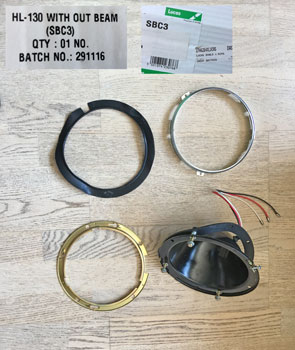
When I went to fit these I found that they were too large. The fixing studs/adjusters which go into a hole in the headlamp part of the bonnet are 7¼" apart, compared to 7" on the car. I queried this with Paul but he did not know of a smaller version which is strange as these are supposed to fit the Spitfire Mklll which is very similar to mine. I've therefore fired off a couple of emails to both Rimmers (who supplied the headlamps) and Auto Electrical Spares who supply lots of headlamp stuff!
Saturday 30th June 2018
Finally finished the fixings for the MTA modular fusebox. As I didn't want to drill any holes in the car, I made up some aluminium bar 15 x 15 x 125mm to which to screw the fusebox. Screw holes were drilled and tapped for M6 button screws. These were glued into the car in the passenger footwell (behind the chassis plate).
Below are the aluminium bars, glued to the inside of the car (just below the battery box).
Monday 9th July 2018
No work done, as preparations for my 70th Party next Saturday, and looking after Liz who has been very ill with a mystery virus, have taken up all my time. The only thing I've done is obtained a new jack handle, and bought some clips to attach it to the underside of the spare wheel board (both from ebay). I've also ordered some 2.5mm bolt sets to attach the clips to the board, The look I am aiming for? See below right (from the GT6 handbook).
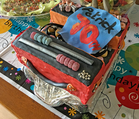
Saturday 14th July 2018
Party day! Around 50 guests arrived to help me to celebrate 70 years on this planet! Garry made me another cake, this time in the shape of a toolbox. Below are this, and his 1998 original.
Wednesday 1st August 2018
Since my last entry not much done, still planning the wiring! My Inguinal Hernia hasn't helped, and Liz has been quite ill with suspected Polymyalgia Rhumatica. What a couple of old codgers we've become!
Monday 10th September 2018
Just finished designing the new wiring looms, drawing them in Drawplus and collating them in one pdf document! For more details see my My GT6/Restoration2/Wiring Loom.
Thursday 13th September 2018
Roughly assembled the headlight to see how I can fit the DRL bulb in the pilot light hole. Below the second picture shows how the inner bowl is in the way of the pilot light hole. The third picture shows where the inner bowl needs to be relieved so the wiring can reach the pilot light hole (to be used for the DRL).
Monday 17th September 2018
As my hernia was less painful today, I started the GT6 and drove it out of the garage so I could replace it in a better position (it was too close to one side). I've made a video with my new camera, which I have posted to Youtube. To see it click here. The engine sounds magnificent, although at the end it missed a bit (perhaps the fuel is running out, I need to put in another can full).
Saturday September 22nd 2018
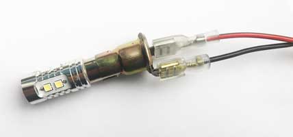
With my Dremel I made the cutout for the wires & connectors to reach the DRL in the pilot hole as last Monday, see below with a terminal inserted (although I won't be using pre-insulated terminals). Next picture is the LED DRL bulb in its 'pilot light' holder. It will be very bright!
I then started assembling the LH headlamp. First I inserted a new "Fix Nut - Simmonds SNO Type", see first picture below (this description comes from the Standard-Triumph Hardware Catalogue). The second picture shows it in situ, the square hole arrowed. . The third picture shows the Headlamp Gasket in position (with the hollow protrusions for the adjusters left and top). The fourth picture shows the Headlamp Bowl fitted with stainless steel self-tapping screws. The holes for the adjusters need to be top and left as well.
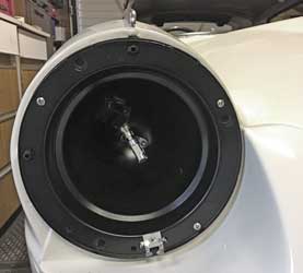
Sunday September 23rd 2018
Continued with the LH headlamp. First below, the adjuster plastic "nut" inserted into the headlamp bowl from behind. Second, the adjuster itself, screwed into the "nut". Third, the spring from the inner to outer bowl.
First below the outer fitted to the inner bowl; second the headlamp fitted with its retaining ring.
The problem now, is how to fit the chrome headlamp rim, which will need a bit of detective work!
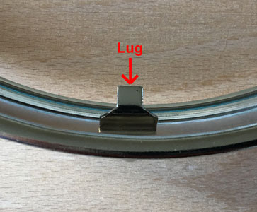
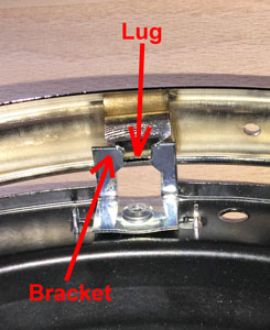
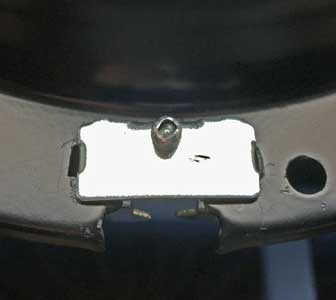
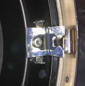
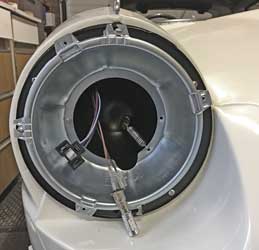
When I bought the headlamp components from Paddocks they included some mysterious metal parts (see below-1) with no instructions as to what to do with them! I couldn't refer to the old ones as they were so rusty I threw them away years ago (without taking photos). I therefore came to the conclusion that the rim hooked over the two arrowed protrusions at the top of the headlamp bowl (below-2) and was normally secured by a screw at the bottom (hence the hole at the bottom of the rim and the bracket at the bottom of the bowl see below-3). The only problem is that because the headlamps are in a recess on the GT6/Spitfire there is no way to access a screw. This is where the purpose of these metal parts became clear! Instead of a screw the bracket at the bottom of the bowl needs to be replaced by the new metal parts which become a bracket onto which a lug at the bottom of the rim clips.
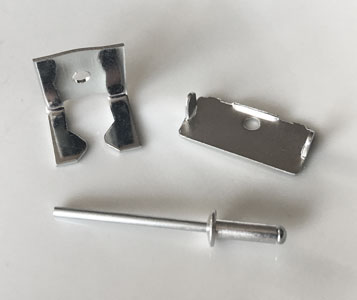
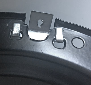
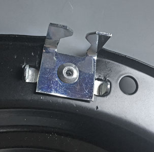
The only problem with this is that the new bracket (see above) is in the wrong position, it needs to be higher up (see below). I tried bending the bracket but it is still not quite right, the bracket needs to be mounted higher up.
Thursday 11th October 2018
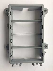
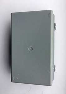
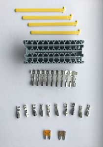
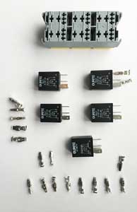
Some fusebox items:-
1. The Shell.
2. The Lid.
3. One of the 2 mini-blade fuse modules with (top to bottom) The yellow
secondary locking bars (slid into place to prevent the terminals being pulled
out); The module; Busbar terminals (consisting of a row of individual terminals
linked on a strip); Fuse terminals; and a couple of fuses.
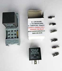
4. (from left to right) Module for 2 mini-relays; an electronic
indicator/hazard "relay" with OE clicking sound; and non-insulated crimp
terminals that accepts 6.3mm wide pins.
5. The module for 6 micro-relays. The 4 relays underneath are 4-pin and the
additional one underneath these is a 5-pin. Various terminals can be seen, at
the bottom small ones for 4.8mm wide relay pins and on the left larger ones for
6.3mm relay pins. For some reason I've only got 5 of the larger ones when there
are 2 per relay - I need 5 more!
Friday 12th October 2018
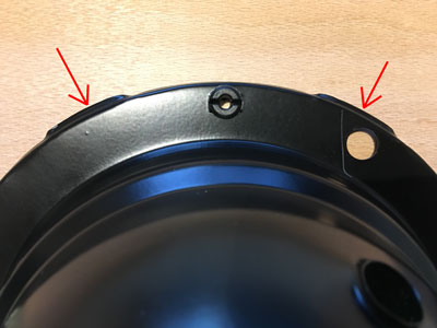
Headlamp rim problem (see Sept 23rd) revisited. I've taken another photo to illustrate this, see below:-
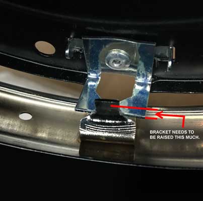
In the end I removed the bracket by drilling out the pop rivet, reversed the rear part drilled a hole through the rear part and the bowl itself and refitted the front part, with the clip, now in a raised position.
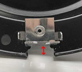
The red arrow shows the amount the bracket was raised. Below we can see that it should now fit i.e. the headlamp rim should attach onto the top 'lugs' and clip at the bottom (see below).
Sunday October 14th 2018
Crimped female spade connectors onto the DRL LED bulb with tool PR4.
Wednesday October 24th 2018
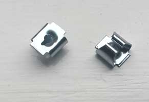
The Fix Nut - Simmonds SNO Type (see September 22nd) was too small so I researched these more and found that the part number on Canleys website was FC2804. Paddocks listed these as 'headlamp bowl to body mounting spire clips for theTriumph Stag! I therefore obtained some, see below.
Thursday October 25th 2018
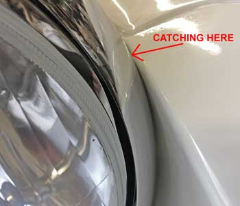
Finally assembled the left headlight, to come against another problem! All the parts went together reasonably well (see below) but when I tried to fit the chrome rim, it wouldn't go on, as the whole assembly was too close to the front bonnet headlamp recess! Incidentally the 4th picture below shows the LED DRL bulb, before insertion into the pilot hole of the headlight unit.
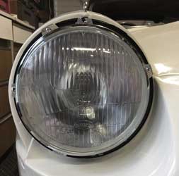
A closeup of the problem. The solution? I'm not sure at the moment, first I'll loosen the screws holding the inner bowl and try to move it to the left.
Sunday 11th November 2018
Recovering from hernia operation last Friday! I hope to resume 'car' activities in due course!
Friday 14th December 2018
Now fully recovered, but it's too cold to work in the garage! The cover's over the car, and just under the front of the car can be seen the o/s headlamp bits - getting these to fit is my first job of 2019, when I must get the car back on the road! The battery's not on charge. I put it on charge before my operation but when I went to get the battery charger to lend to my son, Jason, to charge his SEAT (off the road after accident) it had been unplugged (by my wife?). When I pick him up at Christmas I must get it back as I usually leave it permanently on charge over the winter months.
Sunday 23rd December 2018
Picked up Jason from Manchester yesterday, complete with battery charger, so put the car back on charge today.
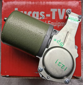
Wednesday 9th January, 2019
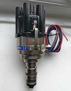
The 123 Ignition TUNE+ electronic distributor arrived from SC Parts Group. I ordered this as a replacement to the existing Delco which, according to Martin Jay of Distributor Doctor is "poor quality, Lucas units were much superior". This dutch made 123, which is configurable by an App in my iPhone, doubles up as a security device as a simple click in the App can immobilise it! First impressions are that it is extremely well made and finished.

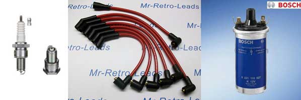
Monday 28th January, 2019
Now I've bought a new distributor, I've decided to upgrade the rest of the ignition system i.e. spark plugs, coil and HT leads (see below). To find our more see my Ignition (Latest Restoration 2) page or click here.
![]()
![]()